VHF 5000 System Functional unit workshop service
3-19
1007
Fig. 1
Fig. 3
Fig. 4
Fig. 5
2
1
4
3
4
2
3
1
Fig. 2
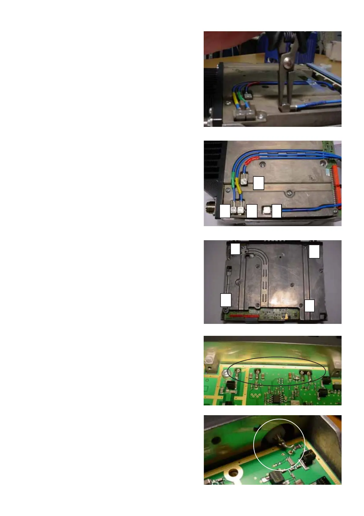
Removal:
• Disconnect 4 x cables connecting duplex filter
to the RF module (See Fig. 1).
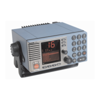
Each cable is identified by a coloured sleeve as
follows (See Fig. 2):
1. Green
2. Yellow
3. Red
4. Blue
Tools required: Flat nose pliers
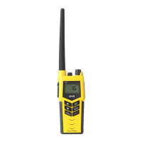
• Remove 10 x screws securing shielding cover of
RF module and remove cover.
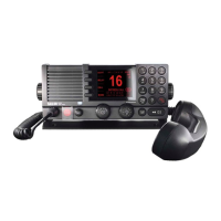
• unsolder the oins of the PA module and slightly lift
these from the RF module.
• unsolder and remove the tinned copper wire
connecting each antenna connector center pin to
the RF module. Retain the tinned copper wires for
subsequent installation of the RF-module
• remove antenna connectors by removing 4 x screws
fastening each connector to chassis.
• remove 4 x screws securing RF module to chassis
and carefully lift out the RF module while being
careful not to bend pins of the PA-module in the
process.
Installing:
• carefully position RF module in chassis while being
observant not to damage or cause excessive
bending of the pins of the PA-module Secure RF
module to chassis by installing 4 x screws, applying
a torque of max. 1.0Nm.
Carefully solder pins of PA module to the RF-
module.
Tools required: Torx screwdriver, size 10
Soldering iron.
• Position antenna connectors in chassis while noting
the correct position of the tapered opening for
soldering and secure each by installing 4 x
screws, applying a torque of max. 1.0Nm.
Tools required: Torx screwdriver, size 10.
• Install and solder each tinned copper wire to the RF
module making sure that the wire just passes
through the module in order not to cause any short
circuiting to chassis.
Solder each copper wire to the respective antenna
connector center pin.
Tools required: Soldering iron, xx watts
• Solder each pin of the PA module to the RF-
module.
Tools required: Soldering iron.