Functional unit workshop service VHF 5000 System
3-24
0608
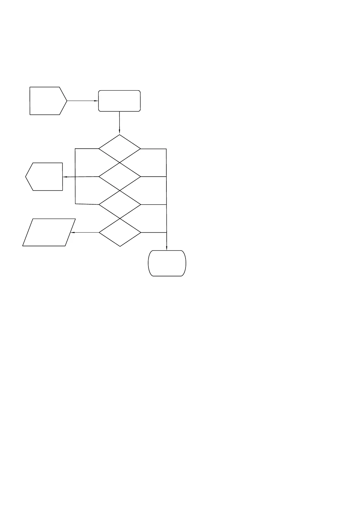
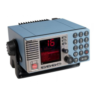
(RTA) - Rx/Tx antenna connection
The Rx/Tx antenna connection is located on the rear right side of the VHF transceiver (see Section “Interface
connections” in the installation section). If you reach this section of the manual, it is because there are
identified problems with either the transmission of Voice/DSC or the reception of a voice signal. Antenna
conditions and antenna installations have been checked OK as well.
(RTA-01)
secure antenna
connector screw
(RTA-02)
RF fail?
40425
(Installation)
Aerials and
cable check
Test Flow
Terminated
Passed
OK
(RTA-03)
Reports?
(RTA-04)
DSC test?
(RTA-05)
DSC test?
(Replace)
Replace PA
(power
amplifier)
Failed
Failed
Failed
Failed
(RF-flow)
Fault finding
RF module
or PA
Passed
Passed
Passed
Fig. 7 (RTA) - Rx/Tx Antenna connection