VHF 5000 System Functional unit workshop service
3-27
(OCVDR) – Option connector VDR interface
The option connector is the upper D-SUB 15 Male connector on the rear side (see Section “Interface
connections” in the installation section). The VDR output is a differential output on pins 1 and 2
This section is consulted after the installation and sanity check of the VDR device has been performed.
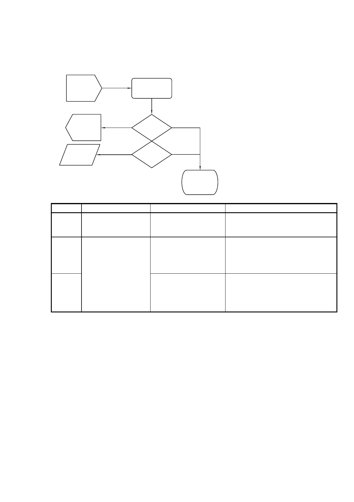
(OCVDR-01)
Secure option
connector screw
(OCVDR-02)
Resceive?
(OCVDR-03)
Transmit?
(Replace)
Replace BB
(base band
board)
Test Flow
Terminated
40431
(Installation)
VDR unit
and cables
Passed
Passed
OK
Failed
(TIC+TIAF
flow)
Transceiver
Failed
(OCVDR-01)
Secure option
connector screw
(OCVDR-02)
Resceive?
(OCVDR-03)
Transmit?
(Replace)
Replace BB
(base band
board)
Test Flow
Terminated
40431
(Installation)
VDR unit
and cables
Passed
Passed
OK
Failed
(TIC+TIAF
flow)
Transceiver
Failed
Fig. 10 (OCVDR) - Option connector VDR test flow
Reference Operation/Test Test Criteria Comments/instructions
The 15-pole DSUB cable connector is fixed
NOTE:
Refer to the installation section for
connector pin ratings.
Pass:
Voice signal received
can be measured on pins 1
and 2.
The signal output on the VDR output is a
0dBm signal.
Fail:
Signal is not measured
OK.
Pass:
Voice signal
transmitted can be measured
on pins 1 and 2.
The signal output on the VDR output is a
0dBm signal.
Fail:
Signal is not measured
OK.
OCVDR-02 Verify received signal is
passed to the VDR output
OCVDR-03 Verify transmitted signal is
passed to the VDR output
OCVDR-01 Secure option connector
Tabel 6 (OCVDR) - Option connector VDR tests
1007