VHF 5000 System Functional unit workshop service
3-33
(SPLO) – SPARC-II connector line output
The SPARC-II connector is the middle D-SUB 15 female connector on the left rear side (see Section “Interface
connections” in the installation section). An auxiliary line output can be used to connect an external audio
amplifier. Received voice is always routed to this output. The received audio line output in the SPARC-II
connector contains any received voice signal. The receiver audio output is located on pins 14 and 15 in the
connector.
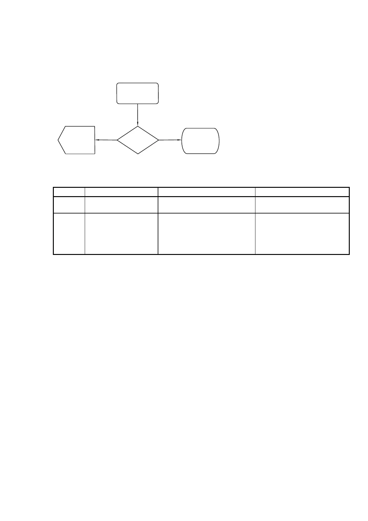
(SPRA-01)
Voice receiver
(SPRA-02)
RX audio
Test Flow
Terminated
40453
Passed
Failed
(TIC+TIAF-
Transceiver
activation
flow)
output?
(SPRA-01)
Voice receiver
(SPRA-02)
RX audio
Test Flow
Terminated
40453
Passed
Failed
(TIC+TIAF-
Transceiver
activation
flow)
output?
Fig. 18 (SPLO) – SPARC-II connector line output validation flow
Reference Operation/Test Test Criteria Comments/instructions
SPLO-01 Activate voice receiver E.g. by turning down squelch
button or run the alarm test from
SPLO-02 Verify received voice data
Pass:
Voice signal is measured OK
between pins 14 and 15. Fail: No
signal measured on option pins 14
and 15
The signal is a fixed normalized
output. No volume control possible
on this pin.
NOTE:
Refer to the
installation section for connector
pin ratings.
Tabel 14 (SPLO) – SPARC-II connector line output validation steps.
(HSC) – Handset connector flow
The handset connector is the lower D-SUB 9 connector on the rear left side of the transceiver (see Section
“Interface connections” in the installation section). The handset connector validation – if problems with the
handset are identified - is best done using a new handset or test equipment emulating a handset (see also
section “Handset block” description).
0608