VHF 5000 System Functional unit workshop service
3-35
Identifying module interconnect errors
As this section requires the opening of the transceiver unit (please refer to the assembly/disassembly sections).
At this stage the following should already be checked:
• All installations have been verified to be sane and operational
• Accessory devices – if connected – have been validated.
• External connector validation flows have been followed.
• Self-test has been executed (menu 5). The result of the self-test execution might be able to lead to some
conclusions while searching for failures.
If one of the tests in this section fails, it would most likely involve the use of a cabling replacement kit. As a
reference for locating the different connectors, please consult the electrical interconnection diagram. Pin
number 1 is always identified by a red wire on the flat cables.
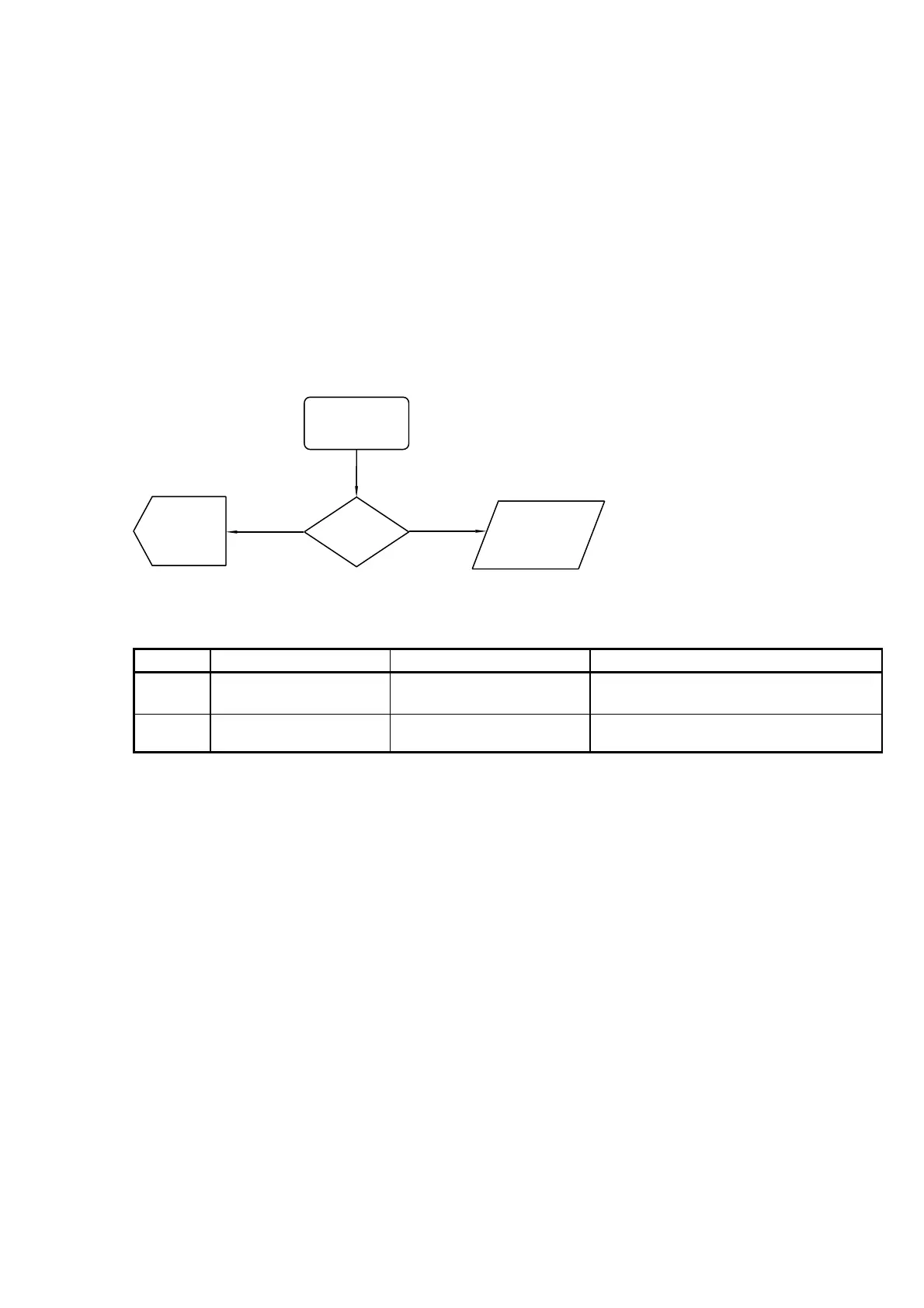
(SPC) – Internal speaker connection
The internal speaker is connected to the baseband PCB. The wires should be visually inspected for errors.
(SPC-01)
Voice receiver
activation
(SPC-02)
Rx audio
40457
Failed
output?
Passed
(Audio-flow)
Audio path
verification
(Replace)
Replace
loudspeaker
(on MKD)
(SPC-01)
Voice receiver
activation
(SPC-02)
Rx audio
40457
Failed
output?
Passed
(Audio-flow)
Audio path
verification
(Replace)
Replace
loudspeaker
(on MKD)
Fig. 20 (SPC) - Speaker connection check
Reference Operation/Test Test Criteria Comments/instructions
SPC-01 Activate voice receiver E.g. by turning down squelch button or run
the alarm test from menu
5.4.
SPC-02 Verify speaker signal
Pass:
Speaker signal can be
measured.
Tabel 16 (SPC) - Internal speaker check.
(MKDC) – Connections to the radio front module
The radio control unit (front module) is connected using three flat cable connections:
• Display connector cable
• Keyboard connector cable
• Light connector cable
The check flow described in the following, is a guideline for identification of which module most likely is failing,
and need to be replaced, after broken cables have been checked.
1007