Note: The RS232 interface can be connected to the eSolar GPRS/4G/WiFi module.
For operation details, please refer to the quick installation guide of each
monitoring module.
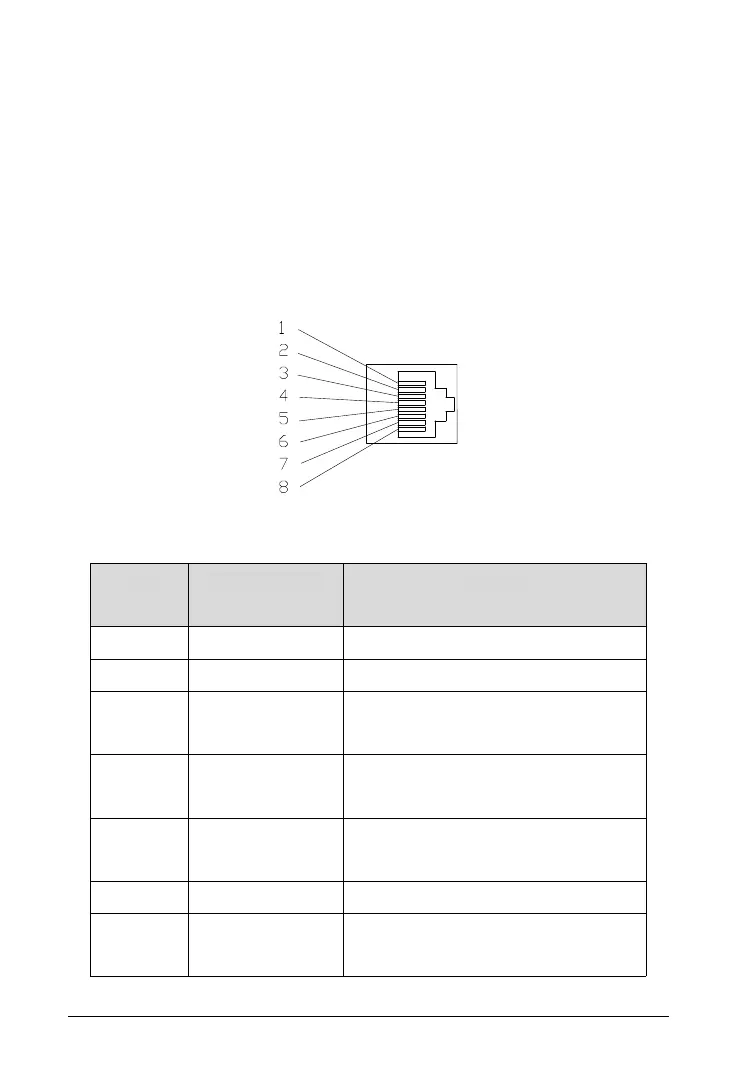
4.5.2 Inverter Demand Response Mode
To comply with Australian and New Zealand safety requirements, the DRMs
terminals should be connected. A RJ45 plug is being used as the inverter DRED
connection.
Fig. 4.7 DRMS pins
Table 4.4 DRMS pins description
The inverter is on standby mode
The inverter is not consuming power
The inverter is consuming less than 50% of rated
power
The inverter is consuming less than 75% of rated
power AND source reactive power if capable
The inverter is consuming 100% of rated power
(Subject to constrains from other active DRMs)
The inverter is not generating power
The inverter is generating less than 50% of the
rated power
 Loading...