Revised 3/30/2010 1.3
Physical Characteristics
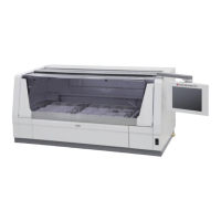
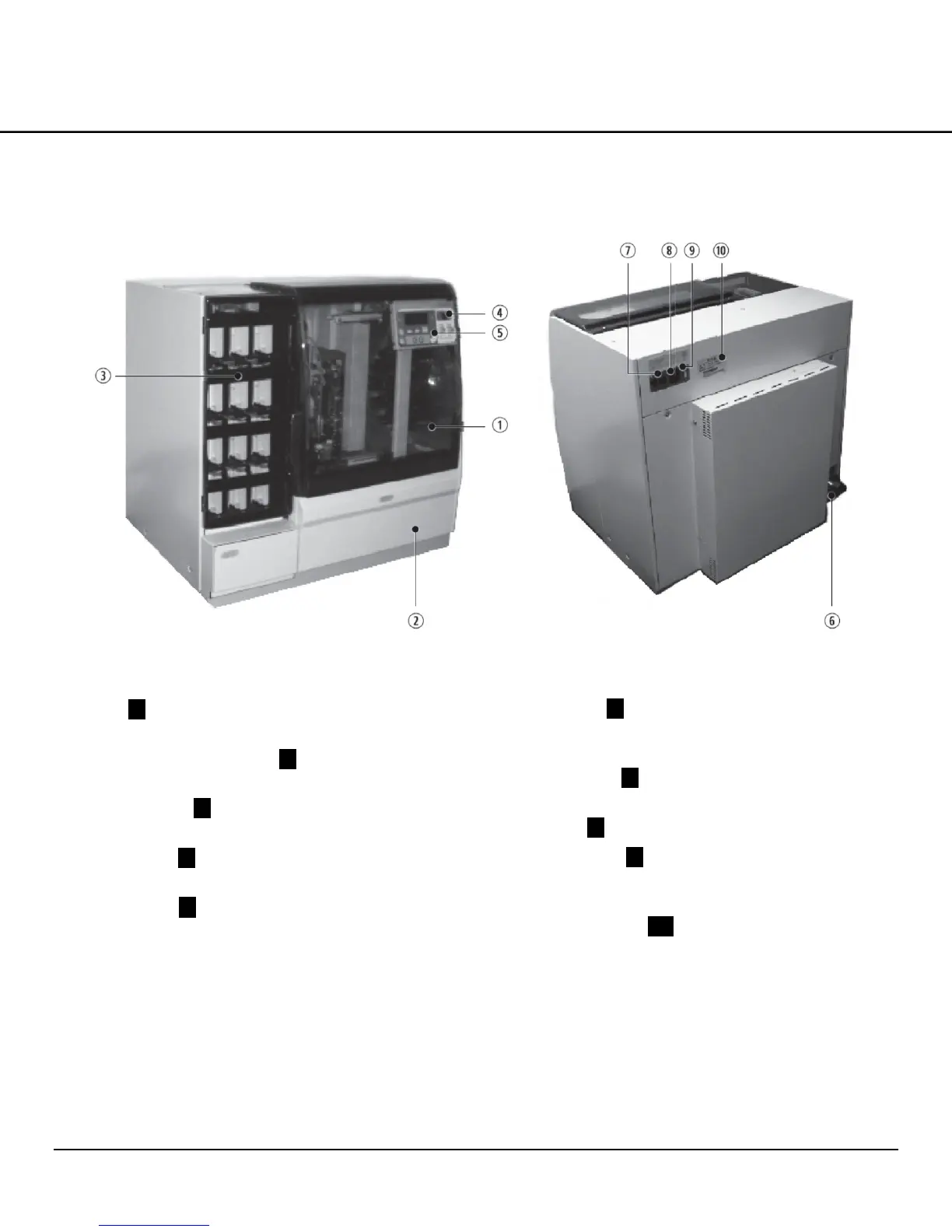
Front Side (Figure 1-B)
Cover .1. — Open this cover to fill cover glass or remove
an empty basket.
Loading station access door .2. —The loading station in
which baskets are placed is found behind this door.
Unloading door .3. —Receiving racks are placed behind
this door.
Power switch .4. —This switch is used to turn the system
power on/off.
Control panel .5. — This control panel is used to operate
the system.
Back Side (Figure 1-C)
Exhaust outlet .6. —Air from the interior of the system is
exhausted through this outlet. An external exhaust duct of
a diameter of 38 mm or 75 mm in size can be connected.
Circuit protector .7. —This is a safety component used
to protect against power surge.
Power inlet .8. —Connect the power cable here.
Contact terminal .9. —When the system is linked to an
automated stainer, these terminals connect to the link
cable.
Serial number label .10. — The serial number of the
system is specified on this label.
Figure 1-B
Figure 1-C
 Loading...