SALMSON 08/2016
Connection terminal allocation
• Loosen the screws and remove the converter
cover.
The terminals IN1, IN2, GND and Ext. Off meet
the requirement for « safe isolation » (in acc.
with EN61800-5-1) to the mains terminals, as
well as to the SBM and SSM terminals (and vice
versa).
Designation Allocation Notes
L1, L2, L3 Mains connection voltage Three-phase current 3 ~ IEC38
PE Earth connection
IN1
(DDS-terminal 9)
Sensor input Type of signal: Voltage (0 - 10 V, 2 - 10 V)
Input resistance: Ri ≥ 10 kΩ
Type of signal: currrent (0 - 20 mA, 4 - 20 mA)
Input resistance: Rb = 500 Ω
Can be congured in the « Service » menu <5.3.0.0>
IN2
(10V/20mA-terminal 7)
External setpoint input Type of signal: Voltage (0 - 10 V, 2 - 10 V)
Input resistance: Ri ≥ 10 kΩ
Type of signal: currrent (0 - 20 mA, 4 - 20 mA)
Input resistance: Rb = 500 Ω
Can be congured in the « Service » menu <5.4.0.0>
GND (x2) Ground connections For both inputs IN1 and IN2.
+ 24 V DC voltage for sensor Load max. : 60 mA
The voltage is short-circuit proof.
Ext. off Control input ON/OFF
« Overriding OFF »
For external potential-free switch
The pump can be switched on/off via the external
potential-free contact.
In systems with a high switching frequency
(> 20 switch-ons/offs/day), switching on/off is to be
done via « ext. off ».
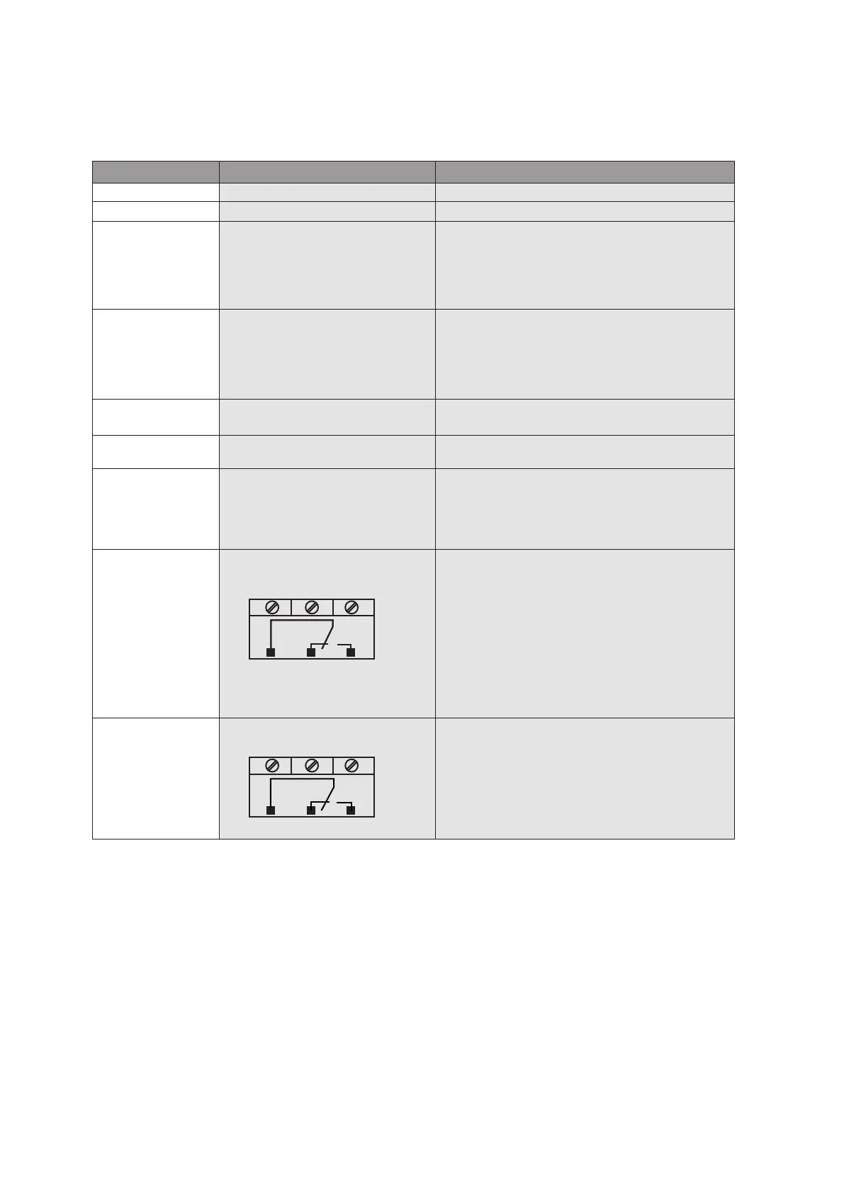
SBM « Available transfer » relay In normal operating, the relay is activated when the
pump runs or is in a position to run.
When a rst defect appears or by main supply cutoff
(the pump stops), the relay is deactiveted.
Information is given to the control box, regarding the
availability of the pump, even temporarily.
Can be congured in the « Service » menu <5.7.6.0>
Contact load:
minimum: 12 V DC, 10 mA
maximum: 250 V AC, 1 A
SSM « Failure transfer » relay After a series of detection (from 1 to 6 according to
signicance) of the same type of defect, the pump
stops and this relay is activated (up to manual action).
Contact load:
minimum: 12 V DC, 10 mA
maximum: 250 V AC, 1 A
English
31