44
English
SALMSON 08/2016
8. Faults, causes and remedies
Faults should only be remedied by qualied per-
sonnel! Observe the safety instructions.
Relays
The converter is tted with 2 output relays
aimed for an interface to centralized control.
ex.: control box, pumps control.
SBM relay :
This relay can be congured in the « Service »
menu < 5.7.6.0 > in 3 operating states.
State: 1 (factory setting)
« Available transfer » relay (normal operating for
this pump type).
The relay is activated when the pump runs or is
in a position to run.
When a rst defect appears or by mains supply
cutoff (the pump stops), the relay is deactiveted.
Information is given to the control box, regarding
the availability of the pump, even temporarily.
State: 2
« Run transfer » relay.
The relay is activated when the pump runs.
State: 3
« Power on transfer » relay.
The relay is activated when the pump is con-
nected to the network.
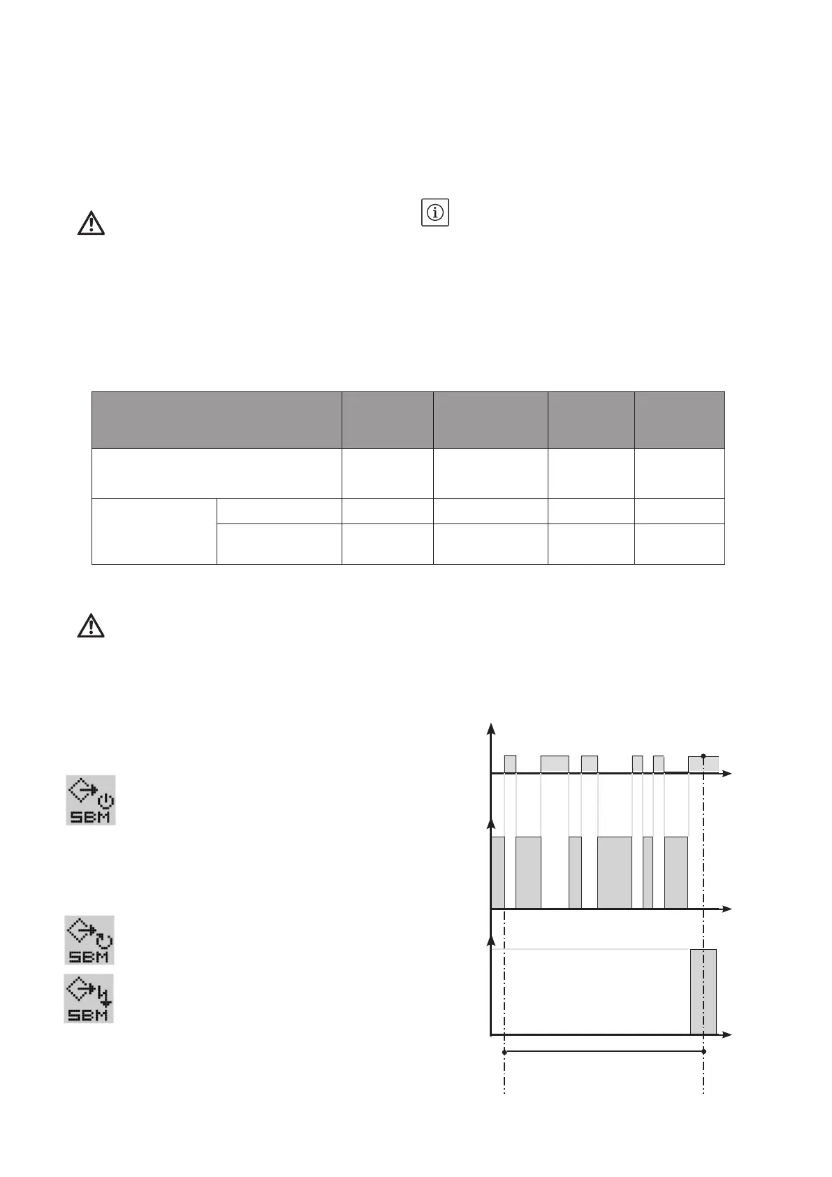
SSM relay:
« Failures transfer » relay.
After a series of detection (from 1 to 6 accord-
ing to signicance) of the same type of defect,
the pump stops and this relay is activated (up to
manual action).
Example: 6 defects with a variable time limit on
24 sliding hours.
State of SBM relay is « Available transfer ».
• In case of failure, do the lling in again and start
the operation again.
• Check that the current input does not exceed
the value indicated on the motor-converter data
plate.
7. Maintenance
DANGER! Before working on equipment, switch
it off and prevent it from being switched on
again!
• No special maintenance in operation.
• The bearing holding the coupling and the motor
bearings are lubricated for their total lifetime and
do not require any lubrication.
• Keep the pump and the motor-converter per-
fectly clean.
• In case of prolonged stopping, if there is no risk
of frost, it is better not to drain the pump.
• To avoid any locking of the shaft and the hydrau-
lic unit during the freezing period, drain the
pump by removing the plug (item 6) and lling
plug (item 5). Screw both plugs back in without
tightening them.
Replacement frequencies
NOTE: These are only recommendations, the
replacement frequency depends on the operat-
ing conditions of the unit , i.e.:
• Temperature, pressure and type of conveyed
uid for the mechanical seal.
• Load and ambient temperature for the motor and
the other components.
• Starting frequency: continuous or intermittent
running.
24H00 sliding
Defects
Active
relay
SBM
Rest
relay
Active
relay
SSM
Rest
relay
1 2 3 4 5
6
Parts or components subject to wear Mechanical seal
Pump and motor
bearings
Converter Motor winding
Indicative operating lifetime
10 000 h to
20 000 h
12 000 h to
50 000 h
≥ 15 000 h
Amb. maxi
40°C
25 000 h
Amb. maxi
40°C
Replacement
frequency
Continuous 1 to 2 years 1,5 to 5 years 1 to 3 years 3 years
15 hours per day
9 months per year
2 to 4 years 3 to 10 years - 6 years