46
The heavy-duty baffled fibreglass tank has a nominal capacity of between 4000 litres (880 gallons) and 5500
litres (1210 gallons) depending on specification and is suitable for all agrochemicals.
The charging hole in the top of the tank holds a large capacity filter basket.
The tank lid is fitted with a breather but if filling is being carried out with a high capacity pump, it is advisable to
remove this lid to prevent excessive pressure build up in the tank.
SPRAY TANK
A large capacity suction filter is fitted on the left-hand side of the machine
behind the rear wheels. The 30-mesh element should be cleaned frequently
to eliminate pump cavitation and loss of spraying pressure. The filter is fitted
in the suction line between the rotary 'suction' tap and the pump. The rotary
'suction' tap may be turned to the ‘unmarked’ position to isolate liquid flow to
the filter.
SUCTION FILTER
The Sight Gauge fitted is usually of the 'float and weight' type. The float is retained in the tank on a stainless
steel guide and is attached to the weight retained within a transparent tube normally fixed to the boom rest or
roger rail.
The top half of the Sight Gauge is visible from the driver's seat and provides a visual indication of when the
tank is nearing empty. Because the float is located close to the center of the tank, an extremely accurate
reading of tank contents is provided at all times.
SIGHT GAUGE
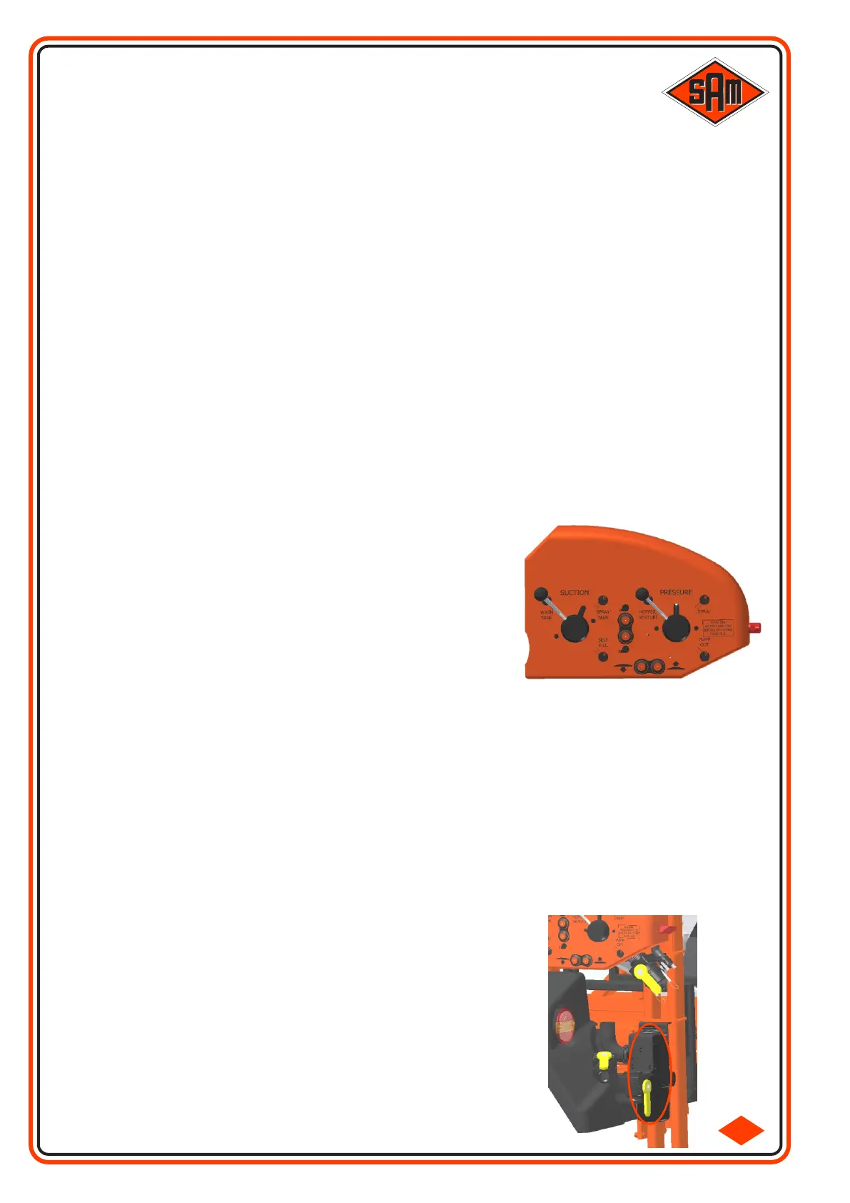
At the rear left-hand corner of the sprayer are two rotary taps. The tap
labeled 'suction' dictates where the spray pump will suck its water from.
This may be from the Main Spray Tank, the Clean Water Tank or from an
outside source, “self fill”. The final position (unmarked) on this tap will
isolate the main filter.
The 'pressure' tap dictates where the spray pump will transfer its water
to. This may be 'spray' for normal use, washing or agitation; 'Hopper
Venturi' so that the induction hopper will operate or 'Pump Out' to transfer
surplus liquid into a holding tank. The protective cap on the 'pump out'
outlet should be removed prior to selecting this position.
ROTARY TAPS
4-1
Also mounted in the rotary tap panel are additional switches for use while the machine is stationary.
Boom lift & lower switches are provided to make easier the removal of the induction hopper from the stowed
position.
Spray pump Speed 1 & 2 switches are also provided for easier control of the induction hopper, self fill or pump
out facility.
Additional switches may also be fitted for various options, not only here but in other locations around the
sprayer e.g. Quick Fill Pump, Pressure Washer, Induction Hopper Light.