SECTION III USE
Load sensing - mechanical lift
The power-lift assembly to control mounted, semi-mounted or towed
implements, consists of an hydraulic unit that performs the following
functions:
–
automatic implement position control;
–
automatic draft control;
–
mixed position and draft control;
–
automatic adjustment of implement lowering speed through
«Valvematic»;
–
quick implement penetration;
–
hydraulic control of external implements.
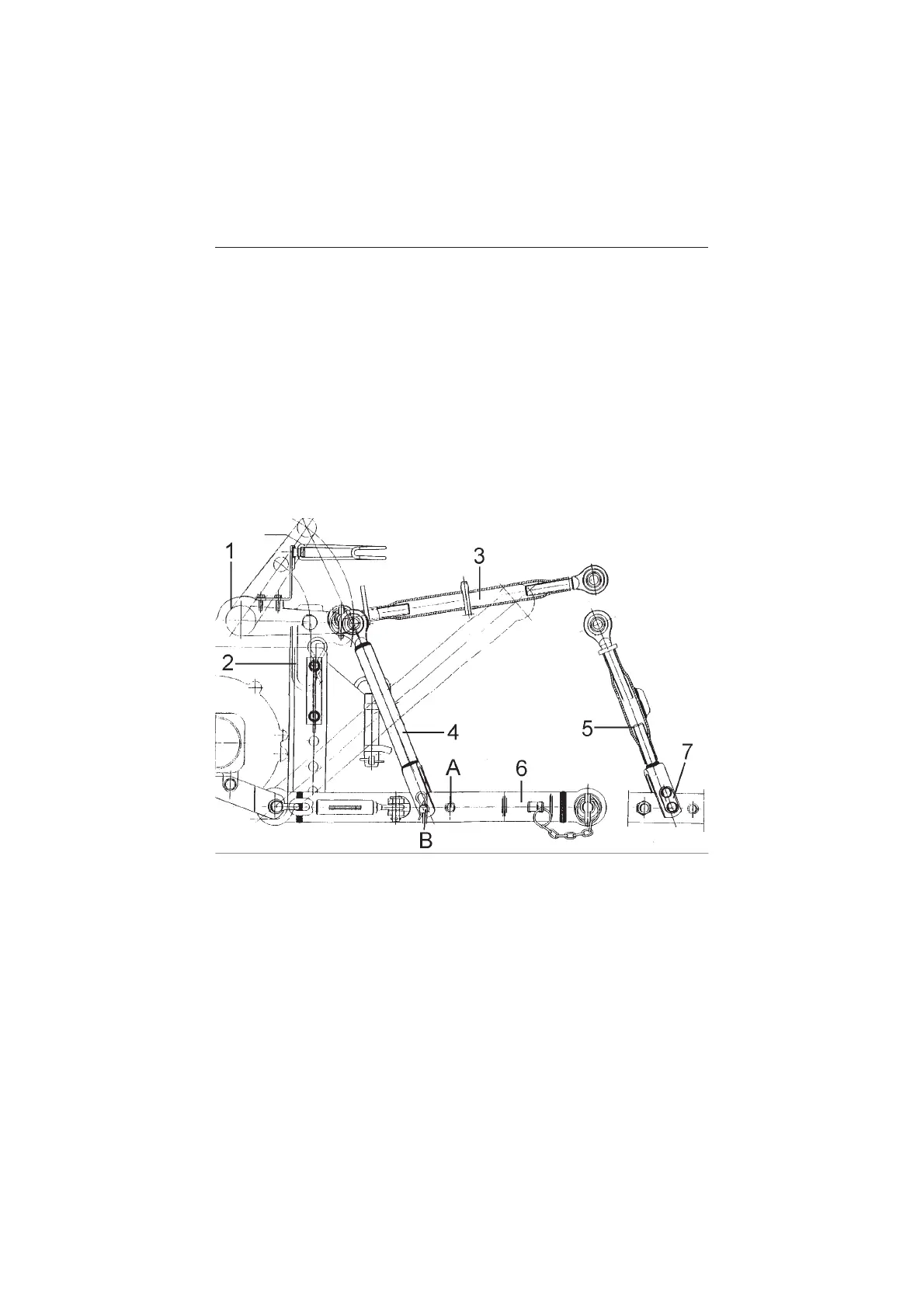
Lifting components diagram (3-point hitch)
1 - Outer adjustment arm
2 - Draft control sprin
3 - Top link
4 - Left lifting arm (stationary)
5 - Right lifting arm (adjustable)
6 - Telescopic stabilizers
7 - Vertical link attaching plate w/pin
A - Lifting capacity is increased when lifting rod is positioned in hole A
B - Lifting height is increased when lifting rod is positioned in hole B
45