Index revision : H 36 6336
7.8. Cable assembly
WARNING : This operation is delicate and must be carried out with extreme care.
7.8.1. Disassembly
• Stage 1: Remove the powder pipe (see § 7.2.1
page 30).
• Stage 2: Unscrew the 4 screws fixing the
handle assembly to the gun.
• Stage 3: Unscrew the 3 electrical connection
wires on the gun and remove it (see § 7.4.1
page 32),
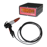
• Stage 4: Unscrew the strain relief (item 2)
Unscrew the stuffing box (item 1) using a 19-
mm flat wrench, unscrew the 3 screws (item 3)
from the base plate (item 4) to separate it from
the handle assembly and lower the base plate
to unscrew the green/yellow wire fixing screw
(item 5).
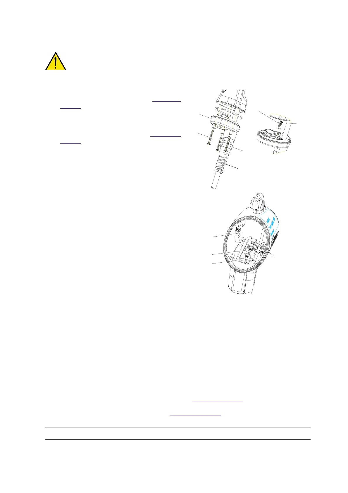
• Stage 5: Remove the box (Hall effect sensor -
Item 8, figure 2) from its housing located behind
the trigger in the upper part of the handle
assembly using a flat screwdriver.
• Stage 6: Unscrew the end-of-handle-assembly
board (item 6, figure 2) and remove it from the
handle assembly.
• Stage 7: Unplug the black connector (item 9,
figure 2).
• Stage 8: Unscrew the strain relief (item 7,
figure 2) located on the shield of the electronic
board.
• Stage 9: Remove the cable from the handle
assembly.
7.8.2. Assembly
• Stage 1: Take a new cable equipped with its base plate.
• Stage 2: Insert the cable into the handle assembly, ensuring that it is correctly positioned (see
figure 2). Be careful not to pass the cable through the powder pipe housing.
• Stage 3: Fix the strain relief (item 6, figure 2) (recovered) to the shield of the board, ensuring that
it is correctly positioned.
• Stage 4: Connect the connector to the board.
• Stage 5: Fix the board (item 5, figure 2) in the bottom of the handle assembly using the two screws.
• Stage 6: Replace the sensor box (item 7, figure 2) in its housing.
• Stage 7: Fix the green/yellow wire (item 4, figure 1) to the handle assembly base plate.
• Stage 8: Reassemble the base plate (item 3, figure 1); retighten the stuffing box to a torque of 3.5
NM, it is necessary to loosen the strain relief on the stuffing box before proceeding with this
operation. Tighten the strain relief on the stuffing box.
• Stage 9: Change the gun seal.
• Stage 10: Reconnect the gun power-supply wires (see § 7.4.2 page 32
).
•
Stage 11: Reposition the gun and handle assembly making sure not to pinch the gun power-supply wires.
• Stage 12: Install the vertical powder pipe (see § 7.2.2 page 30).
DES02715
DES02726
1
3
4
Green/yellow wire
5
Figure 1
Figure 2
6
7
8
2
9