26 | SAMLEX AMERICA INC.
SECTION 2 | Components & Layout
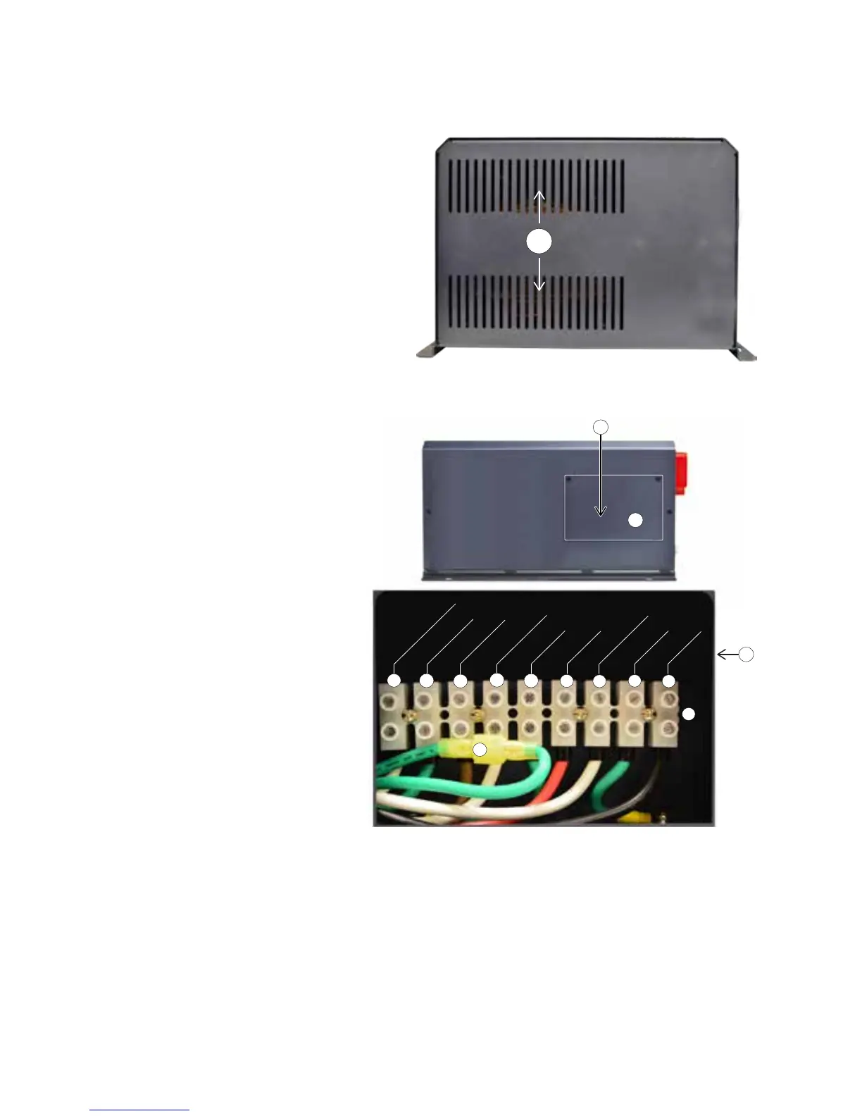
2.3 MAIN UNIT: LAYOUT-AC SIDE (FIG 2.3)
1. Cover plate for pocket for AC Input/Output terminals
2. Pocket for AC Input/Output Terminals (behind cover plate 1)
3. AC Input/Output Terminal Block
Terminal hole diameter: 6mm
for up to AWG #6
Set Screw: M4
4. Grid Input - Line
5. Grid Input - Ground
6. Grid Input - Neutral
7. Generator Input - Line
8. Generator Input - Ground
9. Generator Input - Neutral
10. AC Output - Line
11. AC Output - Ground
12. AC Output - Neutral
13. Male/Female Insulated Quick
Disconnect for disabling Output
Neutral to Chassis Ground bond
in Inverter Mode (Please see
Sections 4.5.1 to 4.5.3 and Fig 3.12)
Fig 2.2 Layout-Back
1
1
13
3
2
[Behind Cover Plate
]
2
9
10
11
4
8
7
6
5
12
OUTPUT NEUTRAL
OUTPUT GND
OUTPUT LINE
GEN NEUTRAL
GEN GND
GEN LINE
GRID NEUTRAL
GRID GND
GRID LINE
2.2 MAIN UNIT: LAYOUT-BACK (FIG 2.2)
1. Air outlet vents for 2 internal fans
Fig 2.3 Layout-AC Side