28 | SAMLEX AMERICA INC.
SECTION 2 | Components & Layout
2.6 CONTENTS OF PACKAGE
Inverter/Charger
Temperature Sensor EVO-BCTS [Fig 2.5(a)]
DC Terminal Covers (1a, 1b: Fig 2.1) (Fitted on the unit with 2 screws each)
Mating Connectors (14, 15, 16: Fig 2.1)
Wire End Terminals for AC Wiring (Fig 3.11)
Model AWG#10 AWG #8 AWG#6
EVO-2212 and EVO-2224 3 6 -
EVO-3012 and EVO-4024 - 9 6
Owner's Manual
Quick Start Guide
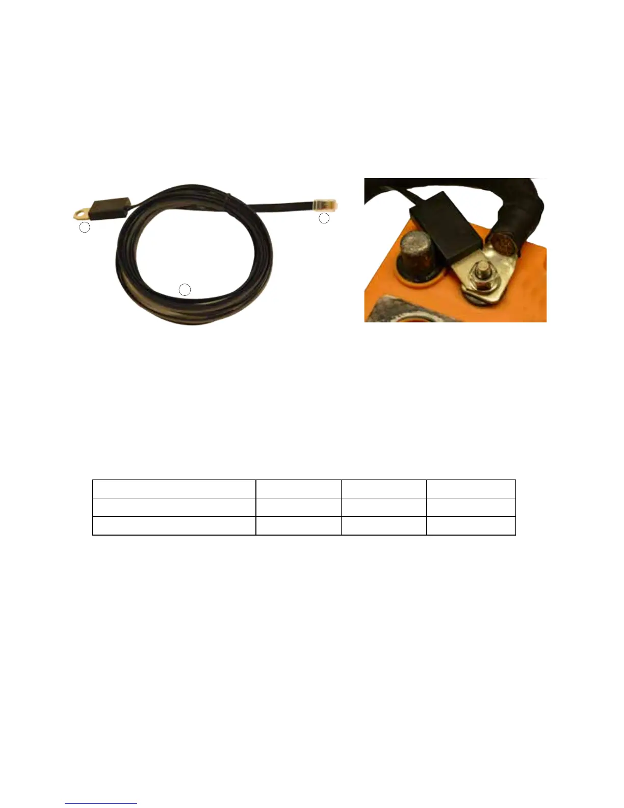
2.5 BATTERY TEMPERATURE SENSOR EVO-BCTS [FIG 2.5 (a)]
Fig 2.5(a) Temperature Sensor Model EVO-BCTS Fig 2.5(b) Temperature Sensor Installation
1. Temperature Sensor: Mounting hole: 10mm/0.39” suitable for 3/8” or 5/16” battery studs
2. RJ-45 Plug
3. 5 meter/16.5 ft cable
Note: Mount the sensor on the Positive or Negative terminal stud on the battery as shown in Fig 2.5(b)