EB 8310-6 EN 3-1
Design and principle of operation
3 Design and principle of operation
The SAMSON Type3271 and Type3277
Actuators with 240, 350 and 700cm² actu-
ator areas are mounted to Series 240, 250,
280 and 290 Valves (globe valves).
3.1 Type3271
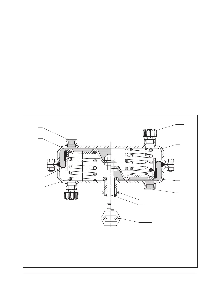
The actuator mainly consists of two dia-
phragm cases (A1, A2), the diaphragm (A4)
with diaphragm plate (A5) and springs
(A10) (see Fig.3-1).
The signal pressure p
st
creates the force F =
p
st
· A at the diaphragm surface A which is
opposed by the springs (A10) in the actua-
tor. The bench range is determined by the
number of springs used and their compres-
sion, taking into account the rated travel. The
travel is proportional to the signal pressure
p
st
. The direction of action of the actuator
stem (A7) depends on how the springs are
installed in the actuator.
A1 Top diaphragm case
A2 Bottom diaphragm
case
A4 Diaphragm
A5 Diaphragm plate
A7 Actuator stem
A8 Ring nut
A10 Spring
A16 Vent plug
A26/27 Stem connector
clamp
S Signal pressure
connection
Version with direction of action
"actuator stem retracts"
Version with direction of action
"actuator stem extends"
A1
S
A4
A10
A7
A8
A26/27
A2
Fig.3-1: Type 3271 Pneumatic Actuator