EB 8310-6 EN 6-5
Start-up
At half the valve travel, the operating range
is between0.2 and 0.6bar.
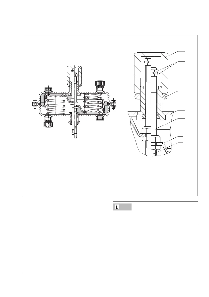
6.2 Travel stop
Refer to Fig.6-2
In the version with travel stop, the maximum
and minimum actuator travel can be limited
as follows:
Direction of ac-
tion
Min. stop Max. stop
Stem extends (FA) 0 to 125% 50 to 125%
Stem retracts (FE) 0 to 100% 50 to 100%
6.2.1 Bottom travel stop
(minimum travel)
1. Loosen top lock nut (A74) and unscrew
cover (A73).
2. Loosen bottom lock nut (A74) and turn
the adjustment nut (A70) to adjust the
travel stop.
3. Tighten bottom lock nut (A74).
4. Attach the cover (A73) and retighten the
lock nut (A74).
6.2.2 Top travel stop (maximum
travel)
1. Loosen top lock nut (A74).
2. Adjust the cover (A73) to the required
travel stop.
3. Retighten top lock nut (A74).
Left half: Actuator stem retracts (FE)
Right half: Actuator stem extends (FA)
A74
A70
A75
A5
A7
A50
A5 Diaphragm plate
A7 Actuator stem
A50 Top actuator stem
A70 Adjustment nut
A73 Cover
A74 Lock nut
A75 Top diaphragm case
Fig.6-2: Travel stop
6.3 Version with handwheel
See Fig.6-3
The stem connector (A51) connects the actu-
ator stem (A7) with the actuator stem (A50)
of the handwheel. The actuator stem position
can be adjusted using the handwheel (A60).
Contact our after-sales service to retrot an
actuator with a handwheel.
Note