9-10 EB 8310-6 EN
Service and conversion work
13. Fasten the top and bottom diaphragm
cases (A1, A2) together using the nuts
(A21) and bolts (A20). Observe tighten-
ing torques.
14. Unscrew the vent plug (A16) from the top
signal pressure connection and screw it
into the bottom connection (S).
The actuator springs, which now push
against the diaphragm plate from below,
cause the actuator stem to retract. The
signal pressure is connected to the top
connection (S) on the top diaphragm
case. As a result, the actuator stem ex-
tends opposing the spring force as the
signal pressure increases.
15. Afx a new nameplate with changed
symbol and new conguration ID to the
actuator.
b) Reversal of the direction of
action from stem retracts to
stem extends
1. Lift off the top diaphragm case (A1).
2. Pull the diaphragm plate assembly con-
sisting of the diaphragm plate (A5), dia-
phragm (A4) and actuator stem (A7) out
of the actuator.
3. Take the springs (A10) out of the bottom
diaphragm case (A2).
4. Unscrew and remove the collar nut
(A15), while holding the nut (A9) station-
ary.
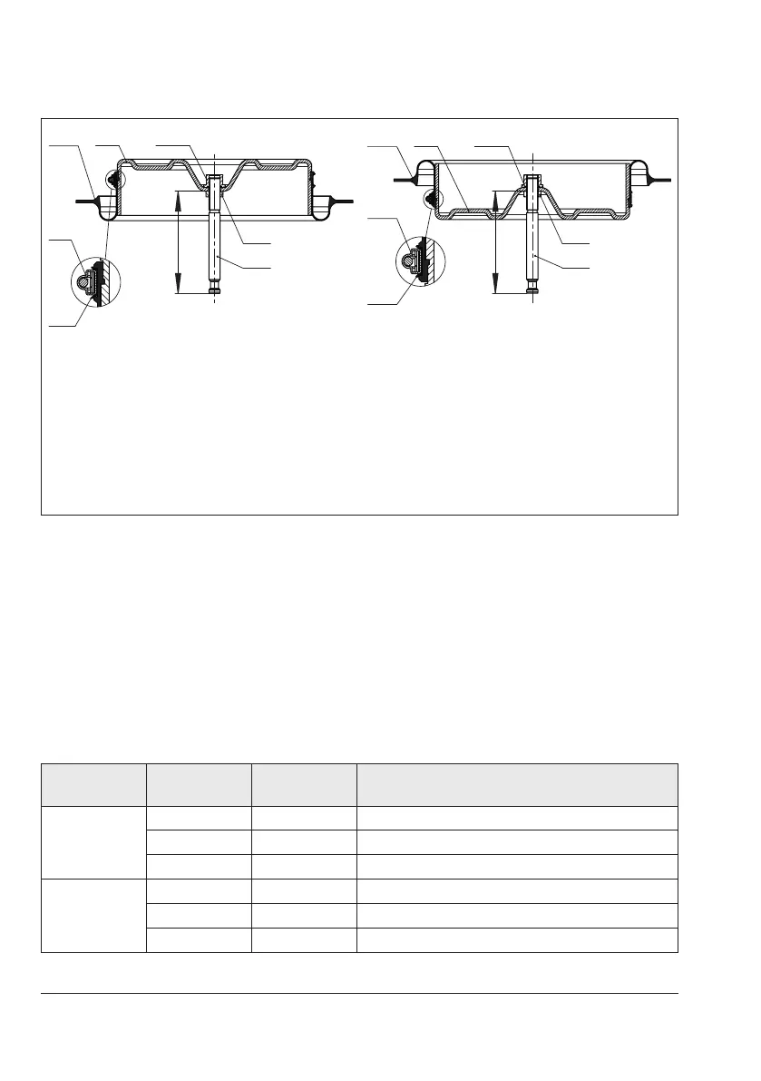
X
A6
A9
A7
A6
A9
A7
X
A4 Diaphragm
A5 Diaphragm plate
A6 Hose clamp
A7 Actuator stem
A9 Hex nut
A15 Collar nut
A19 Compressor
Fig.9-5: Arrangement of parts for "stem retracts" direction of action (left) and "stem extends"
direction of action (right)
Table 9-1: Values for dimension x (see Fig.9-5)
Type Actuator area Travel in mm
Dimension x in mm
(top of the nut to the bottom of the actuator stem)
3271
240 15 98.25
350 15 107.25
700 30 144
3277
240 15 –
350 15 209
700 30 246