EasyManua.ls Logo

Samson C-Control - Wiring Guide; Common Cable Connection Diagrams

Samson C-Control
24 pages
Print Icon
To Next Page IconTo Next Page
To Previous Page IconTo Previous Page
Loading...
17
C•control Wiring Guide
Tip (signal)
Sleeve (ground)
Tip (signal)
Sleeve (ground)
Tip (signal)
Sleeve (ground)
Tip (signal)
Sleeve (ground)
2
3
1
Male XLR
Hot (2)
Cold (3)
Common (1)
End View Solder Points
12
3
Tip (signal)
Cold (Pin 3)
(no connection)
Tip (signal)
Sleeve (ground)
Tip (signal)
Sleeve (ground)
Tip (signal)
Sleeve (ground)
1
3
2
2
3
1
Hot
Cold
Female XLR
Male XLR
Hot (2)
Cold (3)
Common (1)Common
Hot
Cold
Hot (2)
Cold (3)
Common (1) Common
Solder Points End View
End View Solder Points
12
3
21
3
Tip (signal)
Signal (tip)
Signal (ring)
Signal (tip)
Signal (ring)
Ring (signal)
Sleeve (ground)
Ground
Ground
Tip (signal)
Signal (tip)
Signal (ring)
Signal (tip)
Signal (ring)
Ring (signal)
Sleeve (ground)
Ground
Ground
Tip (signal)
Signal
Signal
Sleeve (ground)
Ground
Ground
Tip (signal)Signal
Signal
Sleeve (ground)
Ground
Ground
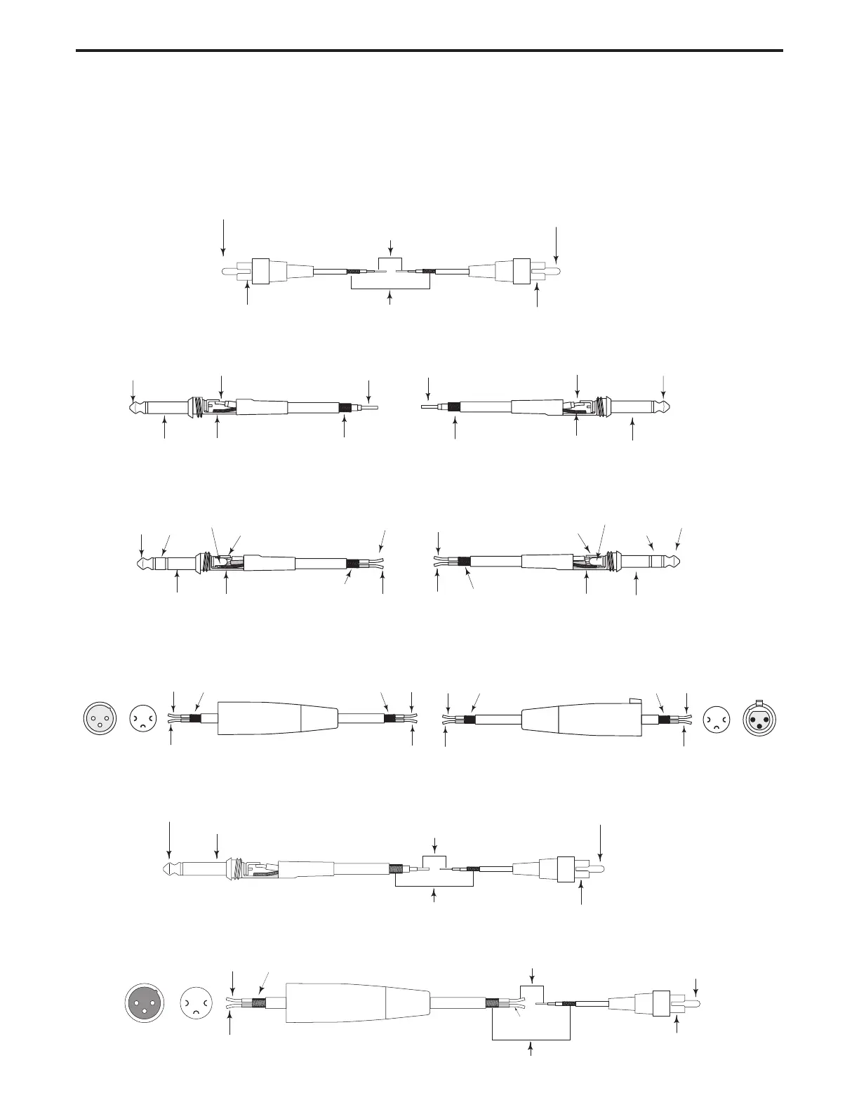
Unbalanced 1/4” to RCA Cable
Un-Balanced XLR to RCA Cable
C control Wiring Guide
There are several ways to interface the C control, depending on your exact monitoring set-up. Follow the cable
diagrams below for connecting your monitor system.
Balanced XLR to XLR Cable
Balanced 1/4” to 1/4” Cable
Un-Balanced 1/4” to 1/4” Cable
RCA to RCA Cable

Related product manuals