3-14 EB2111/2121/2123 EN
Design and principle of operation
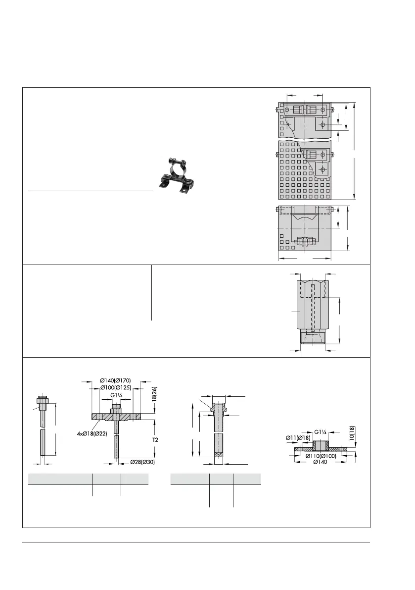
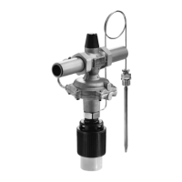
Dimensional drawings
To mount the set point adjuster or sensor to a wall, suitable
clamps (photo) are available.
The clamps for the sensor are integrated into the perforated
cover.
Clampwithbracket
For set point
adjuster
Item no.: 8395-0039
For sensor Item no.: 8395-0037
Types2232/2233/2234/2235·Clamps and perforated cover
for wall mounting
8
35
60
30
Extension piece
Standard version
L=approx.140mm,approx.0.5kg
With bellows (special version)
L=approx.180mm,approx.0.6kg
Separating piece with seals
L=approx.55mm,approx.
0.2kg
L
1)
Add the dimension L to H and H1 when these accessories are used.
Type2231/2232·Thermowells Type2231/2232·Thermowells
for ammable gases (PN100)
Type2233/Type2234·Flange
T2
L2
L1
G1
Thermostat 2231 2232
Immersion depth T2 325 250
Thermostat 2231 2232
Length L1 315 255
Length L2 340 280
FlangePN6;140mmouter
diameter
FlangePN40/DN32
(dimensions in parentheses)
Fig.3-6: Dimensions of accessories·Dimensions in mm