4-13
LAN Port
The RJ-45 connector for LAN port connection is located on the front panel of the MGI card. The
LAN port is connected to the Internet network through network equipment such as the switching
hub.
RS-232C Port
This port is connected to a PC and is used when executing the monitor program for the MGI
card. Use an RS-232C cable to connect with the serial port of the PC.
Reset Button
This button is used to restart the MGI card.
J3 Connector
This connector is used when upgrading the CPLD within the MGI card.
LED INDICATIONS
There are a number of LED indicators on the front of the MGI1/2 card showing the status of the
card. The indications are described in Appendix A
.
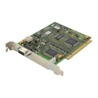
MGI3Card
The MGI3 card (Figure 4-23) supports the VoIP Gateway, which enables telephone calls through
the Internet using IP telephones.
When an MGI3D/ITM3D daughterboard is installed on the card, it can support up to 16 VoIP
ports. Up to two MGI3 cards can be installed in a single cabinet. Insert each card into any
universal card slot. Push firmly in the middle of both card ejectors to ensure the card is firmly
seated into the backplane connector.
LED INDICATIONS
There are a number of LED indicators on the front of the MGI3 card showing the status of the
card. The indications are described in Appendix A
.
VDIAL Card
The VDIAL card (Figure 4-24) is used for making calls by voice rather than by pressing phone
keys. Since the power is supplied to the card’s RAM through the 1F condenser C5, the
memory’s contents are stored for approximately one week if the VDIAL card is disconnected
from the system.
To delete the contents stored on the RAM, discharge the condenser C5 by short-circuiting the
two pins of the mail pin J2 device with a conductor.
The operating mode of the card is set in MMC programming and is one of the following:
• 2 channels, 7 users, 20 bins (total 280 bins)
• 1 channel, 5 users, 40 bins (total 200 bins)
VDIAL has one jumper (JP1) and the location of the shunt pin is determined by the PCM coding
law A-Law or µ-Law (A-Law in the UK).