7-4
Chapter 7
Connecting Station Equipment
Dect Base Station (DBS)
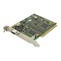
The DBS provides DECT cordless communications and requires an 8BSI card installed in slot 1,
2, or 3. ‘S’ and ‘M’ systems allow one 8BSI card while ‘L’ systems allow up to three (in the same
cabinet, slots 1–3). Each card supports up to eight DBS. Using two pair twisted wire—#24 AWG
(0.5mm) for up to 600m, or #26 AWG (0.4mm) for up to 400m—connect MDF cables to the 8BSI
card (see Figure 4-18
in Chapter 4) and make a connection between the 8BSI card and the DBS.
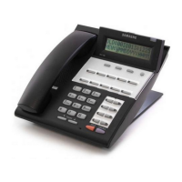
ISDN Station (ISDN Phone, G4 FAX, etc)
Using two pair twisted #24 AWG (0.5mm) or #26 AWG (0.4mm) wire, cross connect each ISDN
TE to the BRI card’s ‘S’ mode port (see Figure 6-6b
in Chapter 6). As NT2, the BRI card sup-
ports S points for ISDN TEs (ISDN phone, G4 FAX, etc). This S mode (ISDN Station Interface
Mode) must be programmed in MMC 423 first, since its default state is T mode (ISDN Trunk In-
terface Mode). Also, MMC 419 is used to determine whether power is supplied to that port. After
programming the BRI card, it must be restarted using MMC 418. Refer to the Samsung Com-
bined System Programming Manual for details of MMC programming.