R
Ryan LawsonAug 21, 2025
What to do if my Samsung RD080PHXEA shows an over current error?
- DDonna ClarkAug 21, 2025
To address an over current issue in your Samsung Heat Pump, reduce the load on the system and inspect all electrical connections.
What to do if my Samsung RD080PHXEA shows an over current error?
To address an over current issue in your Samsung Heat Pump, reduce the load on the system and inspect all electrical connections.
How to fix current sensor error on Samsung RD080PHXEA Heat Pump?
To resolve a current sensor error on your Samsung Heat Pump, replace the current sensor.
What to do if my Samsung RD080PHXEA displays discharge temp sensor error?
To fix the discharge temperature sensor error (short/open) on your Samsung Heat Pump, replace the discharge temperature sensor.
What to do if my Samsung RD080PHXEA displays cond temp sensor error?
To fix the condenser temperature sensor error (short/open) on your Samsung Heat Pump, replace the condenser temperature sensor.
What to do if my Samsung Heat Pump displays outdoor temp sensor error?
To fix the outdoor temperature sensor error (short/open) on your Samsung Heat Pump, replace the outdoor temperature sensor.
What to do if my Samsung Heat Pump shows over temperature of OLP thermistor?
To address the issue of an over temperature of the OLP thermistor in your Samsung Heat Pump, allow the system to cool down before checking the thermistor.
Why Samsung RD080PHXEA Heat Pump is in prohibited cooling mode?
If your Samsung Heat Pump is in a prohibited cooling mode due to outdoor temperatures being under 10°C or inlet water temperature being out of range (5°C ~ 55°C), switch to heating mode or wait for the outdoor temperature to increase.
What to do if my Samsung RD080PHXEA shows an over-load prevention control error?
To resolve an over-load prevention control issue with your Samsung Heat Pump, allow the system to cool down before restarting it.
Why is my Samsung RD080PHXEA in prohibited heating mode?
If your Samsung Heat Pump is in a prohibited heating mode due to outdoor temperatures being over 35°C or inlet water temperature being out of range (5°C ~ 55°C), switch to cooling mode or wait for the outdoor temperature to decrease.
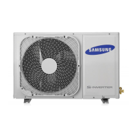
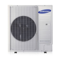
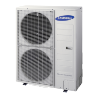
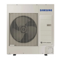
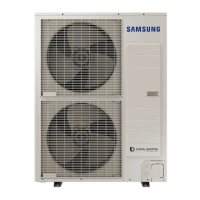
Details the physical appearance and models of outdoor units.
Lists supplied accessories essential for installation.
Shows compatibility between various indoor and outdoor units.
Details compatibility of subsidiary materials with different unit types.
Guidelines for selecting the optimal installation location for the outdoor unit.
Lists places and conditions where outdoor unit installation is prohibited.
Provides general recommendations for installing the outdoor unit.
Specifies required clearances around the outdoor unit for ventilation.
Details clearance requirements when installing multiple outdoor units simultaneously.
Table showing outdoor and indoor unit compatibility and capacities.
Lists general tools and tools for test operations.
Instructions for safely moving the outdoor unit.
Guidelines for moving the unit using personnel.
Steps for disassembling the leg base and wood palette.
Steps for fastening anchor bolts after palette removal.
Instructions for correctly installing the outdoor unit on its base.
Diagrams and dimensions for outdoor unit base mounting and anchor bolts.
Procedures for installing the drain pipe correctly.
Important caution when installing the heating air direction cover.
Details on using manifold gauge, vacuum pump, and flare nuts.
Specifications for pipe lengths and height differences for installation.
Piping length and height difference details for specific models.
Guidance on selecting appropriate refrigerant pipes based on capacity.
How to select and install Y-joints based on unit capacity.
Instructions to seal pipes to prevent foreign materials and water entry.
Steps for cutting and flaring refrigerant pipes correctly.
Guidance on selecting and applying insulation for refrigerant pipes.
Procedures for insulating and brazing refrigerant pipes.
Steps for using nitrogen gas during brazing.
Instructions for installing Y-joints and connecting outdoor unit pipes.
Procedure for conducting a gas leak test using nitrogen.
Detailed steps and procedures for vacuum drying the system.
Guidance on calculating and adding extra refrigerant.
How to determine additional refrigerant based on pipe specifications.
Regulations and procedures for charging refrigerant.
Instructions for adding refrigerant in cooling and heating modes.
General cautions and guidelines for electrical connections and installation.
Wiring diagrams for standard and EEV kit power cable connections.
Details on power and communication cable specifications.
Instructions for running cables through electrical conduit.
Detailed wiring diagram for 1 phase 2 wires connection.
Steps for connecting power terminals and installing earth wires.
Overview of option switches on the outdoor unit PBA.
Explanation of the functions of keys on the outdoor unit PBA.
Details the display and functions associated with pressing the K4 key.
Shows the maximum number of connected indoor units per outdoor unit.
Configuration settings for various dip switches (K5-K12).
Settings for cooling capacity compensation using switches.
Settings for night silence operation.
Settings for heating capacity compensation.
Settings for electric current options based on unit capacity.
Explains the purpose and safety precautions for pump down operation.
Procedure to collect refrigerant before pump down.
Procedure for recovering large amounts of refrigerant.
Checks for outdoor/indoor unit installation, refrigerant, drain, and wiring.
Checks to perform before starting test operation.
Procedures for conducting the test operation.
How to fill out and store the installation check card.
Error codes and meanings displayed on the outdoor unit PCB.