CW-6300 Series
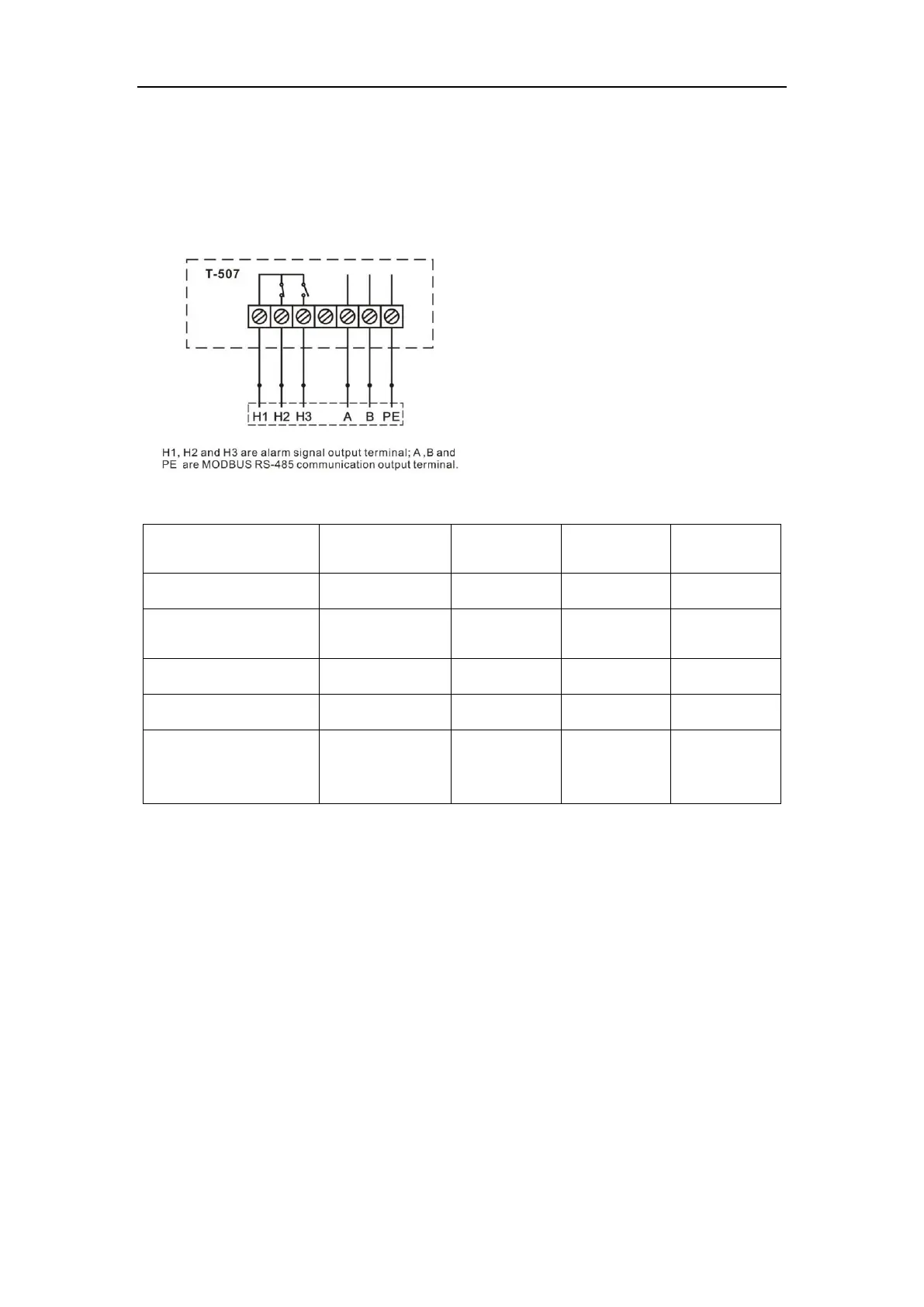
<5> Alarm and communication output
For ensuring the equipment will not be damaged when abnormal condition occurs
in the chiller, it has alarm protection function.
1. Alarm and MODBUS RS-485 communication output wiring diagram.
2. Working condition table of alarm signal
Built-in buzzer of
temp. controller
E00、E01、E05、E06、
E07、E08、E09、E11
Activate after
output terminal
delaying
Note: The flow alarm is connected to the normally open relay and normally closed
relay contacts, requiring operating current less than 5A, working voltage less
than 300V.