S&C Instruction Sheet 716-502 11
Before Starting
CAUTION
Do not remove the containers from the interrupters or
the plastic bubble-wrap from the insulating support
columns until the installation is complete.
NOTICE
Bolted and Pinned Connections: A typical bolted
connection requires a flat washer underneath the cap
screw and one under the nut. When self-locking hex
nuts are specified, it is essential that the threads of the
associated cap screw are lubricated with a general-
purpose grease to facilitate tightening. All pins and cotter
pins used in field assembly should also be lubricated to
facilitate insertion.
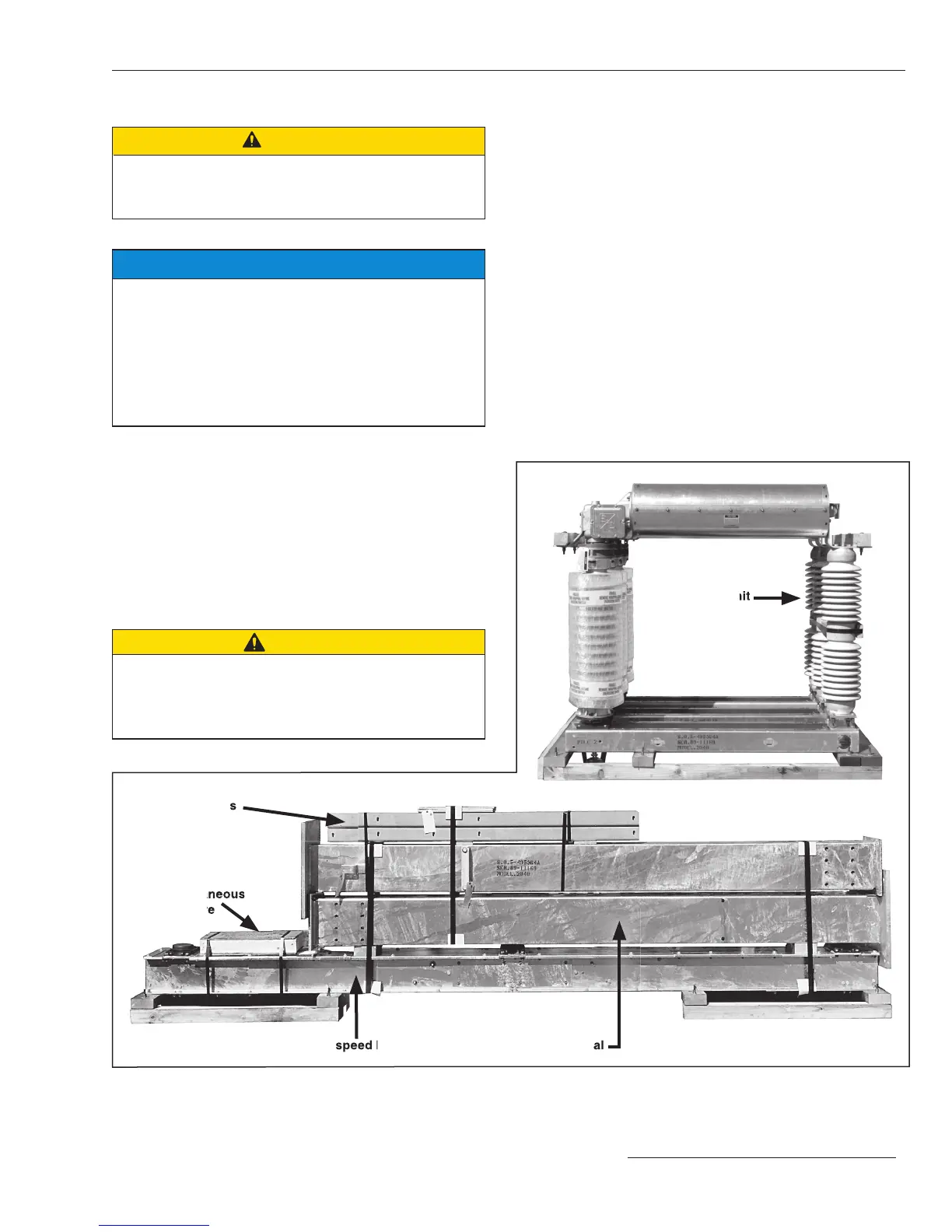
STEP 1. Cut the steel straps that bind the mounting pedestals
to the high-speed base. Cut the straps binding the
container of operating mechanism components and
hardware and the straps binding the pole-units.
Remove any wood bracing between the terminal
pads. See Figure 2.
For circuit-switchers rated 161 kV and 230 kV:
Remove and discard the lifting angles attached to
the pole-unit bases.
CAUTION
The foundations and anchor bolts for S&C Mounting
Pedestals must be designed to meet the loading limits
specified in S&C Data Bulletin 716-61. Failure to meet
these loading limits can result in equipment damage.
Installation
Figure 2. Typical shipment of Model 2040 Series 2000 Circuit-Switcher. Operator is shipped on a separate skid.
Miscellaneous
hardware
High-speed base
Support arms
Mounting pedestal
Pole-unit
 Loading...


