18 S&C Instruction Sheet 716-502
CAUTION
Keep fingers clear of the transition lever’s travel.
The transition lever is under pressure and could quickly
rotate counterclockwise. Injury to the fingers could
result.
(c) Remove the ⅜ -inch stainless steel connecting pin
used to attach the transition lever to the operating
rod link. See Figure 12 on page 17. The pin is locked
in place by a retainer. Lift and turn the retainer to
remove the pin. Keep the pin for re-use in Step 13(e)
(d) Attach the insulated operating rod end links to the
interphase drive linkage lever in the high-speed
base using the ½-inch silicon-bronze pin and cotter
pin retained from Step 12(d). See Figure 13 on page
17. The insulated operating rod may be moved up or
down, as required, to make the connection.
(e) Replace the ⅜ -inch stainless-steel connecting pin
retained from Step 13(c). See Figure 12. It will be
necessary to loosen the 5/16-18 × 2-¼ -inch hex-head
stainless-steel screw, holding the spacer in place,
and withdraw it approximately ⅛ -inch, so the
connecting pin can be inserted. Do not remove the
screw at this time.
(f) After the connecting pin has been inserted, lock it in
place with its retainer.
(g) Remove and discard the 5/16 -18 x 2-¼ -inch hex-head
stainless-steel screw, spacer and stop bracket
(marked with a black/yellow striped label) shown in
Figure 12 on page 17.
Connecting the Operator to the High-Speed Power
Train
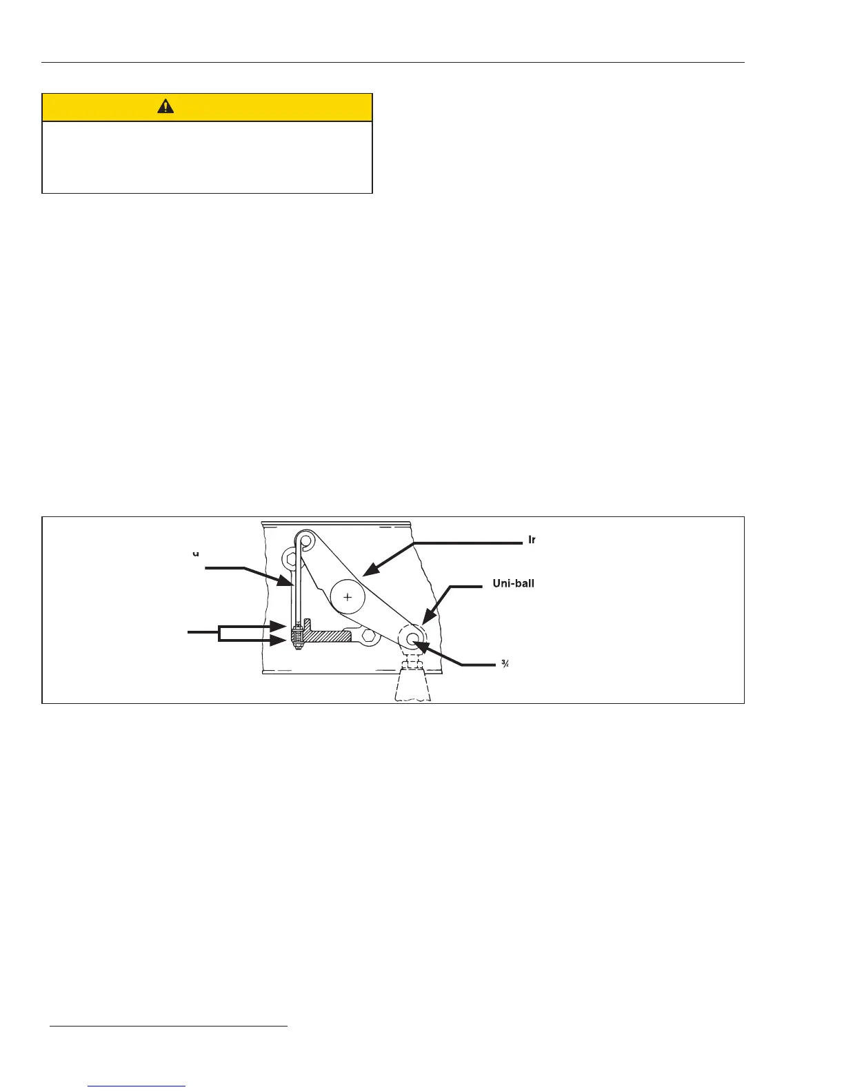
STEP 14. Attach the uni-ball coupling on the operator
connecting link to the interphase drive lever in the
high-speed base using the ¾ -inch stainless steel pin
and cotter pin retained from Step 8. See Figure 14.
An adjustable locking rod (marked with a black/
yellow striped label) is furnished factory-connected
to the interphase drive lever. Turn the associated
¼ -20 locknuts as required to raise or lower the
interphase drive lever enough to facilitate insertion
of the stainless steel pin.
STEP 15. After the pin is installed, remove the lower ¼ -20
locknut that retains the adjustable locking rod, and
then remove and discard the adjustable locking rod
and locknuts. See Figure 14.
Figure 14. Attach the Uni-ball coupling to the interphase drive lever.
Interphase drive lever
Adjustable locking rod
(marked with a black/
yellow striped label)
¾ -inch stainless steel pin and cotter pin
Uni-ball coupling
¼ -inch–20 locknut
Installation
¾ -inch stainless steel pin and cotter pin
 Loading...


