S&C Instruction Sheet 716-502 19
Connecting Conductors
STEP 16.
DANGER
Conductors must be de-energized and
grounded in accordance with standard system
operating practice. Failure to do so can result
in serious injury or death.
Attach the high-voltage conductors to their respective circuit-
switcher terminal pads using exible-conductor connections.
Observe the terminal-pad loading limits speci ed on the
catalog drawing. Use the following procedure for attaching
the conductors:
(a) Thoroughly wire-brush the current-transfer
surfaces of each connector and immediately apply a
liberal coating of Penetrox® A (available from
Burndy Corporation) or other suitable aluminum
connector compound to the brushed surfaces.
(b) Wire-brush each terminal pad and apply a coating of
Penetrox A. Then, bolt the connectors to the terminal
pads.
(c) Prepare the conductors using established
procedures and clamp them in their respective
connectors.
Removing the Interrupter Containers
STEP 17. Remove the container from each interrupter as
follows:
(a) Remove and discard the ⅜ -16 zinc-plated serrated
hex nuts that run the length of the container.
(b) Remove and discard the ⅜ -16 × ⅞ -inch and two
⅜ -16 × 1-inch zinc-plated hex-head cap screws and
at washers that attach the upper container half to
the coupling end casting of the interrupter. Also,
remove and discard the ⅜ -16 × ⅞ -inch and two
⅜ -16 × 1-inch zinc-plated hex-head cap screws and
at washers that attach the upper container half to
the indicator-end casting of the interrupter.
(c) Pry the container halves apart with a at-head
screwdriver or other sturdy pry tool. The upper
container half can now be removed and discarded.
Slotted holes are provided so a rope or lifting sling
can be attached and the container half more safely
lowered to the ground.
(d) Remove and discard the ⅜ -16 × ⅞ -inch hex-head
cap screw and at washer that attach the lower
container half to the coupling-end casting of the
interrupter, and the ⅜ -16 × ⅞ -inch hex-head cap
screw and at washer that attach the lower container
half to the indicator-end casting of the interrupter.
Then, discard this container half.
(e) Remove and discard the foam-core inner liner
wrapped around the interrupter.
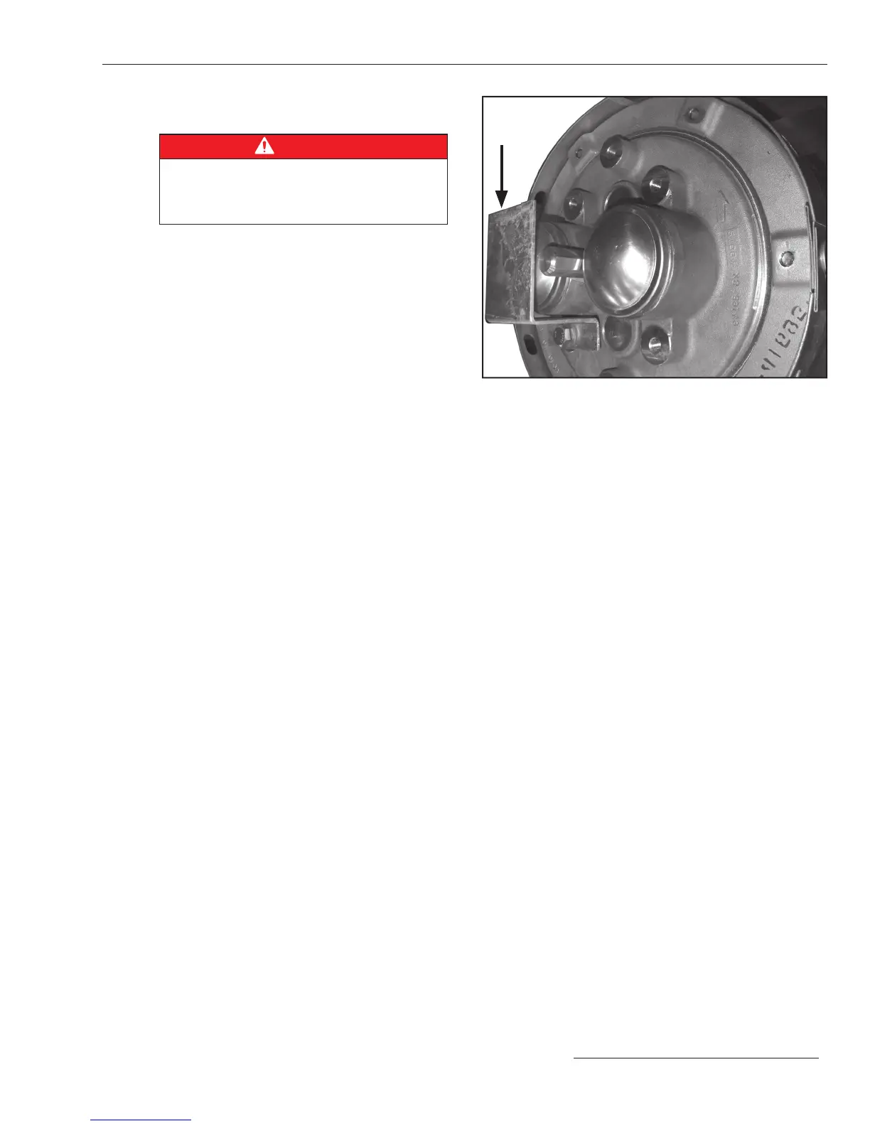
(f) Finally, remove the shield for the pressure-relief
device. See Figure 15.
STEP 18. Remove and discard the wrappers from each
insulating support column.
Figure 15. Remove the shield for the pressure-relief device.
Installation
Shield
 Loading...


