S&C Instruction Sheet 716-502 17
CAUTION
The insulated operating rod is under pressure.
Removal of the shipping bracket may result in the
operating rod quickly moving down approximately
⅜ -inch (9.5 mm). Keep hands clear of the operating
rod when removing the shipping bracket.
(d) Remove the ½ –inch silicon-bronze pin and cotter
pin from the insulated operating rod. Retain these
pins for re-use in Step 13(d).
(e) Remove the protective cover on the high-speed base
at the pole-unit mounting position. See Figure 5 on
page 13. Raise the pole-unit to its mounting position
at the center of the high-speed base, as shown on the
catalog drawing. Carefully guide the pole-unit to
avoid damaging the insulated operating rod.
(f) Attach the pole-unit base to the high-speed base,
using the ½ -13 × 1-¾ -inch hex-head galvanized-steel
cap screws, at washers, and self-locking hex nuts
furnished. Lubricate the cap screws to facilitate
tightening. Securely tighten all cap screws.
(g) Attach the pole-unit base to the support brace,
using the ½ -13 × 1-¾ -inch hex-head galvanized-steel
cap screws, at washers, and self-locking hex nuts
furnished. Lubricate the cap screws to facilitate
tightening. Securely tighten all cap screws.
(h) Install shims as necessary between the pole-unit
base and the support brace to compensate for any
irregularities between the mating surfaces.
Repeat for the pole-units—marked “Pole 1” and “Pole 3.”
Connecting the Pole-Units to the High-Speed Power
Train
STEP 13. Prepare the insulated operating rod of each pole-
unit for attachment to the interphase drive in the
high-speed base as follows:
(a) Remove the six 5/16-18 × ¾ -inch hex-head stainless
steel cap screws used to attach the access cover to
the side of the transition box. See Figure 11. Remove
the cover and place it and the hardware on a clean
surface.
(b) Check that the transition lever is in the open
position. The lever should be turned fully
counterclockwise. See Figures 11 and 12. If the
lever is not in the Open position, carefully turn the
transition lever to the Open position.
If the transition lever cannot be freely rotated to
its fully counterclockwise position, misalignment of
the interphase drive is occurring in the high-speed
base. Swing the insulated operating rod end links
up, away from the interphase drive linkage lever,
and try rotating the transition lever to its fully
counterclockwise position.
Figure 11. Transition lever in shipping position
5/16 —18 ¾ hex-head stainless-steel cap
screws for access cover (removed)
screws for access cover (removed)
Transition
lever
Transition
Box
Operating rod link
Transition lever in shipping position
Figure 12. Transition lever in open position
5/16 —18 x 2 ¼ hex-head
stainless-steel screw
Transition lever in shipping position
⅜ stainless-steel connecting pin
stainless-steel connecting pin
stainless-steel connecting pin
Connecting
pin retainer
Stop bracket (marked with a black/
yellow striped label)
Spacer
(marked with
a black/yellow
striped label)
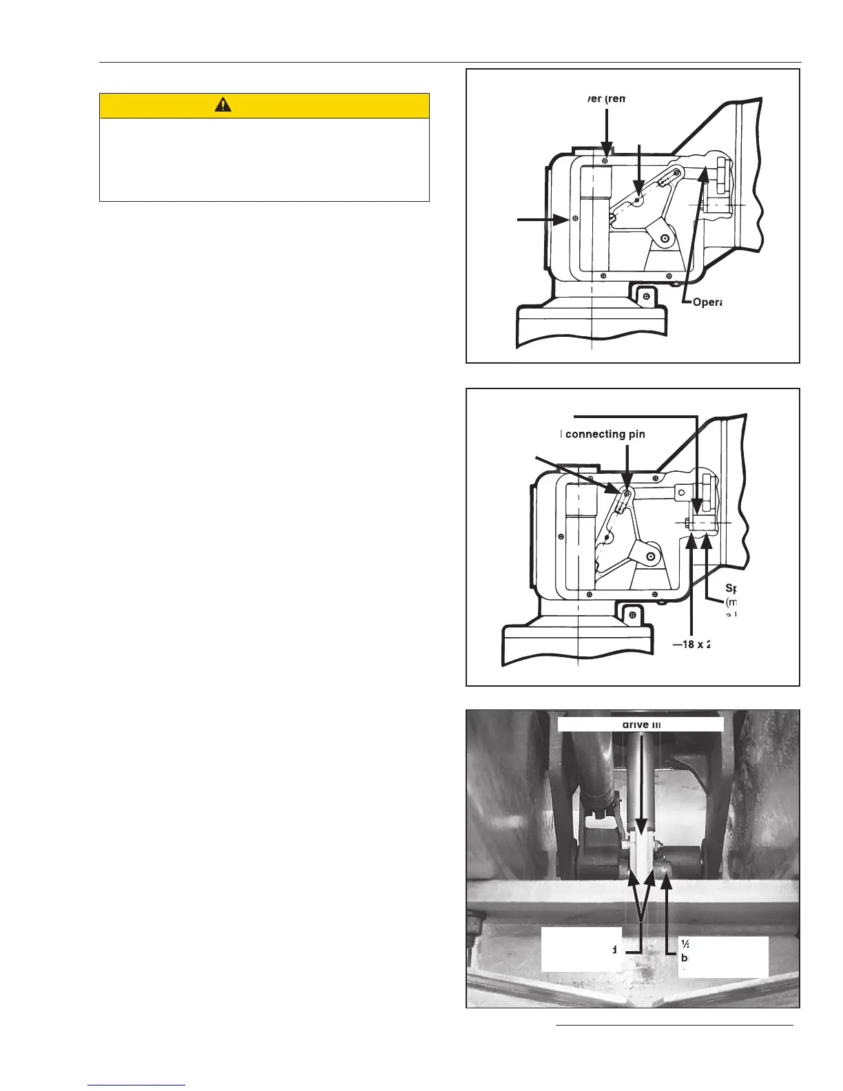
Figure 13. Attach insulated operating rod to interphase drive.
½ -inch silicon-
bronze pin and
cotter pin
Insulated
operating rod
end links
Interphase drive linkage lever
Interphase drive linkage lever
Installation
 Loading...


