14 S&C Instruction Sheet 716-502
Installing the Switch Operator
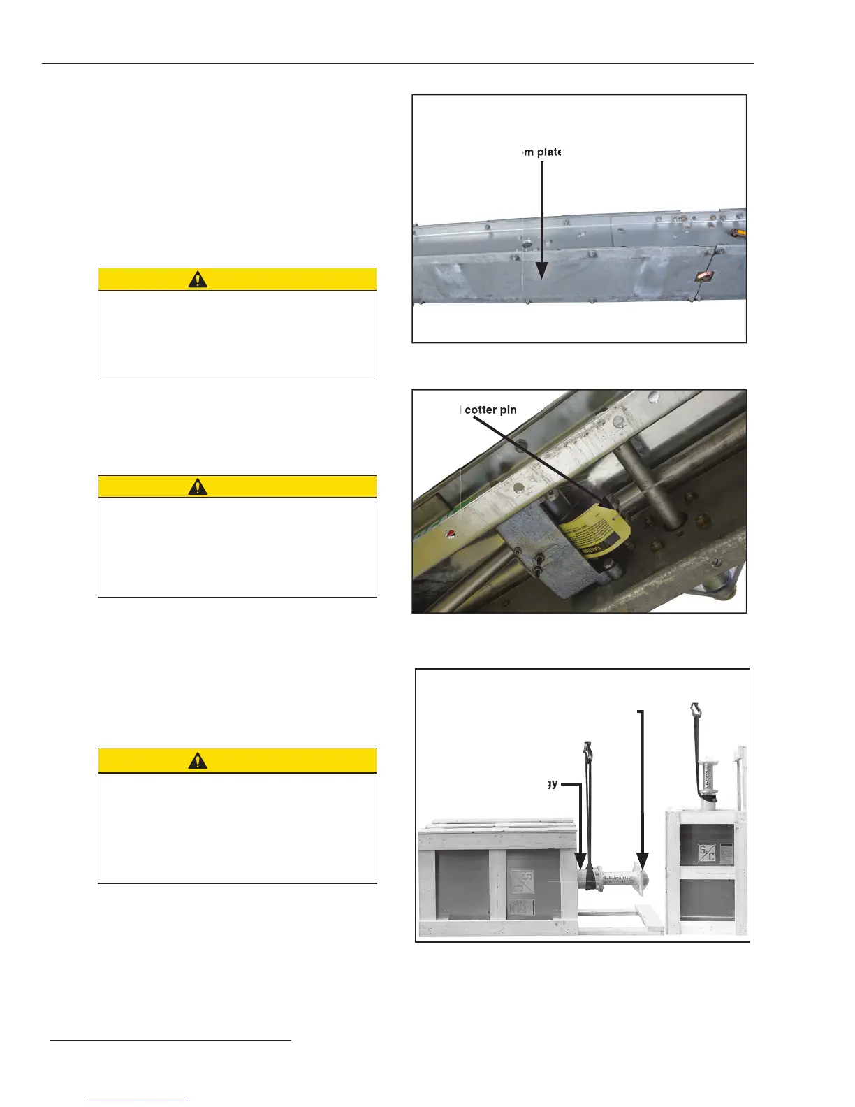
STEP 8. Loosen the ½ -13 × 1-¼ -inch galvanized steel cap
screws, at washers, and nuts attaching the bottom
plates to the underside of the high-speed base.
Remove the plates and place them and their
hardware aside on a clean surface. See Figure 6.
Remove the ¾ -inch stainless steel pin and cotter
pin from the interphase drive lever enclosed in the
high-speed base. See Figure 7. Retain the pin and
cotter pin for re-use in Step 14 on page 18.
CAUTION
Do not attempt to set the operator upright
by slinging to the skid. The skid is not
designed to carry the weight of the switch
operator. Damage to the operator and minor
personal injury may result.
STEP 9. Wrap a lifting sling around the stored-energy
housing of the operator, as shown in Figure 8 (left).
Now carefully raise the operator to the upright
position so that it rests on its base skid, as shown
in Figure 8 (right).
CAUTION
DO NOT remove the lifting sling around
the stored-energy housing after raising the
operator. The operator is top-heavy and must
be adequately supported until it is attached to
the high-speed base. Damage to the operator
may result.
Remove the skid and bracing that runs the
length of the operator, the stored-energy housing,
and the operator support tube. See Figure 8. Also
remove the protective cover and packing on top of
the operator support tube as well as the packing on
the operator enclosure louvers. See Figure 8, and
Figure 9 on page 15.
STEP 10. Lift and install the operator as follows:
CAUTION
Be careful not to damage the uni-ball coupling
on the operator connecting link during hoisting
and attachment of the operator. The uni-
ball coupling cannot be replaced in the field.
Damage will necessitate returning the operator
for replacement.
(a) Reposition the lifting sling around the front of the
stored-energy housing and wrap another lifting
sling around the back of the stored-energy housing,
as shown in Figure 9 on page 15. Make sure the
operator door faces the same way as the switch-
position indicator on the high-speed base.
Figure 7. Remove the ¾-inch stainless-steel pin and cotter pin
from the interphase drive lever inside the high-speed base.
Pin and cotter pin
Figure 8. (Left and Right) Typical shipment of Series 2000 Opera-
tor. Wrap lifting slings around stored-energy housing to raise the
operator to the upright position.
Stored-energy
housing
Packing
Figure 6. Remove bottom plates from high-speed base.
Bottom plate
Installation
 Loading...


