20 S&C Instruction Sheet 716-502
Setting up the Operator and Checkout
STEP 19.
CAUTION
Unauthorized changes should not be made in
the wiring of the operator. Should a control-
circuit revision appear desirable, it should be
made only on the authority of a revised wiring
diagram that has been approved by both the
user and S&C Electric Company.
Do not apply control voltage to the
operator at this time!
Perform the following set-up procedure on the
operator. (See Figures 16 through 18.)
(a) To avoid accidentally energizing the operator after
the external connections have been completed,
open the control power KNIFE switch, and then
swing the KNIFE switch retainer arm out of the way
by putting pressure on the red insulated retainer and
the black nylon retainer nut. The KNIFE switch
retainer arm will “pop up” and can then be swung
out of the way. See Figure 17 on page 22.
(b) Mark the conduit-entrance location for the control-
circuit wiring on the conduit-entrance plate in the
bottom of the operator enclosure. See Figure 16.
Remove the plate and cut out the necessary opening.
Apply sealant and replace the plate. Make up and
connect the entrance ttings, and verify the ttings
are properly sealed to prevent water ingress.
NOTICE
Make sure the polarity of the control circuit
is correct on dc-control voltage models.
Energizing the switch operator with polarity
reversed will cause damage to the operator
control circuit and will require repair or
replacement of the operator.
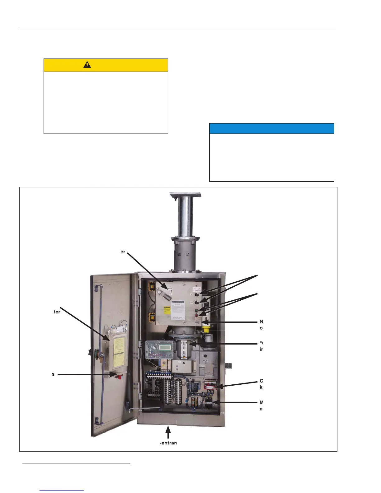
Manual trip lever
Conduct-entrance plate
Motor-and-closing
circuit fuse holder
Control-source
knife switch
Non-reset electric
operation counter
Position indicating
lamps (catalog number
supply suffix "-M"
Trip and Close pushbuttons
"Charged" and "Discharged"
indicators for stored–energy
mechanism
Instruction
Manual holder
Spare fuses
Figure 16. Interior of the switch operator.
Installation
"Charged" and "Discharged"
 Loading...


