12 S&C Instruction Sheet 716-502
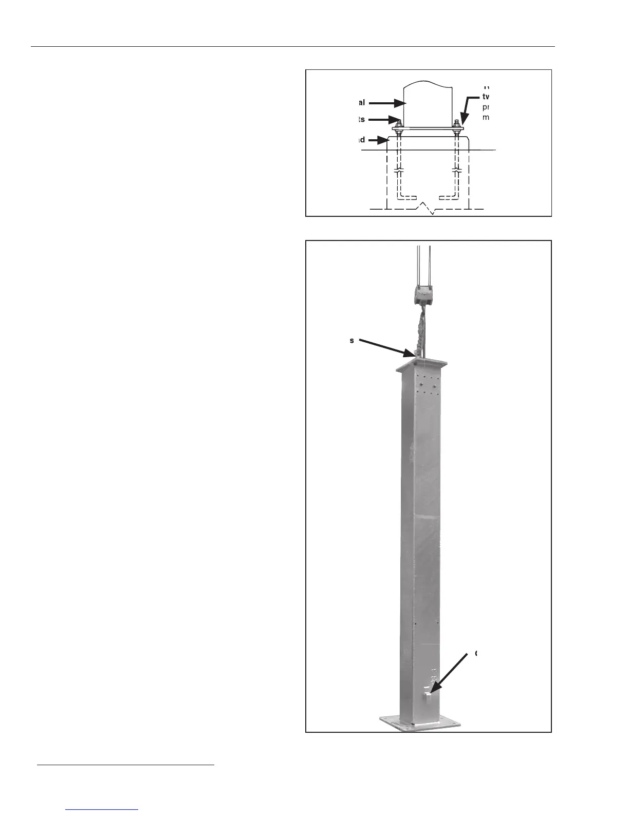
Figure 3. Pedestal anchor-bolt mounting detail.
Two nuts and
two flat washers
provide leveling
means
Pedestal
Anchor bolts
Concrete pad
Figure 4. Lift the pedestal into position.
Eye bolts
Grounding pad
Installing the Mounting Pedestals and High-
Speed Base
STEP 2. Install each pedestal as follows:
(a) Install the lower set of anchor bolt nuts and at
washers onto the pre-installed anchor bolts. Level
all anchor bolts the same height, leaving space
below and above for leveling. See Figure 3.
(b) Install the temporary eyebolts into the holes
provided at the top of the mounting pedestal. Attach
lifting slings to the eyebolts. See Figure 4.
(c) Lift the pedestal over the anchor bolts. Before
lowering, make sure the grounding pad is positioned
properly for the installation. See Figure 4. Refer to
the accompanying catalog drawing for details.
(d) Lower the pedestal onto the anchor bolt nuts and
at washers. Loosely secure a at washer and nut to
each anchor bolt above the pedestal base. See
Figure 3. Remove the lifting slings and eyebolts.
(e) Adjust the lower set of anchor-bolt nuts to plumb
and level the pedestal. The upper set of anchor bolt
nuts should remain loosely attached. See Figure 3.
STEP 3. Attach the support arms to the mounting pedestals,
as shown on the catalog drawing, using the ⅝ -11 ×
1-¼ -inch hex-head galvanized steel cap screws and
at washers furnished. See Figure 1 on page 10.
Lubricate the nuts to facilitate tightening. Securely
tighten the cap screws. Also install the covers on
top of the mounting pedestals, as shown on the
catalog drawing, using the ½ -13 × 2-inch hex-head
galvanized steel cap screws, at washers, and self-
locking hex nuts furnished. Lubricate the cap
screws to facilitate tightening. Securely tighten the
cap screws.
STEP 4. Attach four suitable lifting slings to the high-speed
base. See Figure 5 on page 13. Unbolt the high-speed
base from the shipping skid and lift the base on top
of the support arms, as shown on the catalog
drawing. Verify the switch-position indicator on
the base is visible on the desired side. This is also
the side on which the operator door will open.
Installation
 Loading...


