S&C Instruction Sheet 716-502 21
(c) Connect the external control-circuit wiring
(including the space-heater source leads) to the
terminal blocks at the bottom of the enclosure.
Refer to the wiring diagram. Observe correct
polarity on the dc-control-voltage models. Trip-
circuit conductors and motor-closing circuit
conductors must be adequately sized for the
ampacities indicated on the wiring diagram.
NOTICE
Trip-circuit conductors and motor-and-closing
circuit conductors must be adequately sized
for the ampacities indicated on the wiring
diagram.
DO NOT apply control voltage to the operator
at this time.
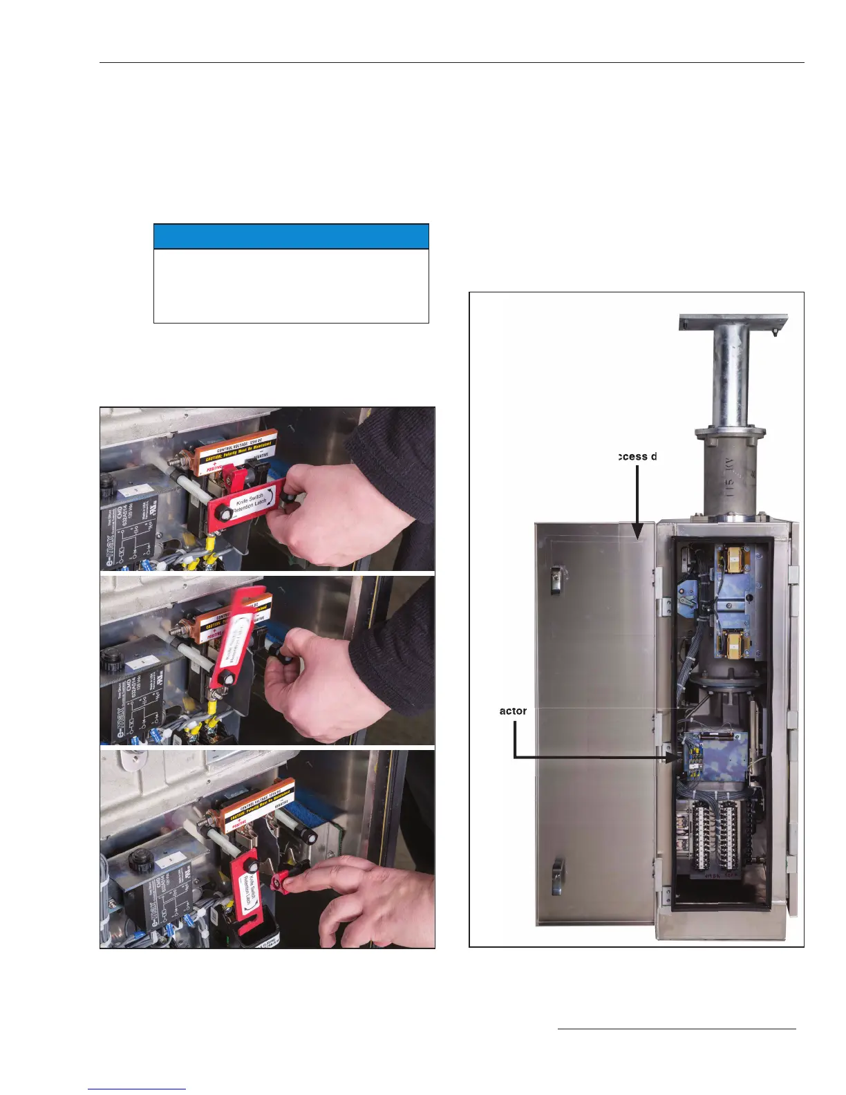
Figure 18. Side-access panel of switch operator.
Side access door
Motor
contactor
Figure 17. The knife switch retainer and knife switch.
Installation
 Loading...


