16 S&C Instruction Sheet 716-502
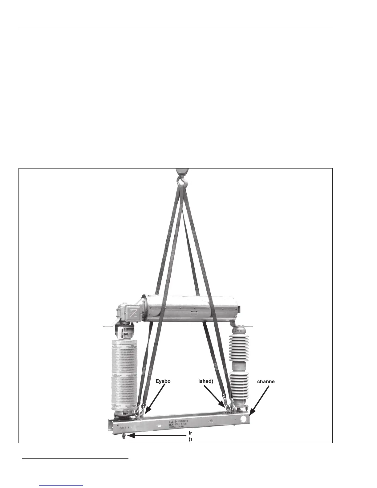
STEP 12. Lift and install the pole-units as follows:
(a) Install four eyebolts on each pole-unit base.
See Figure 10.
(b) Attach four suitable lifting slings to the eyebolts on
the pole-unit to be mounted at the center of the high-
speed base—marked “Pole 2”— as shown in
Figure 10.
(c) Make certain the rigging does not stress the pole-
unit. Unbolt the base from the skid. Raise the pole-
unit a few feet, then remove the two ½-13 × 1¾ -inch
hex-head galvanized steel cap screws, at washers,
and hex nuts that attach the shipping bracket to the
bottom of the pole-unit base. The shipping bracket
protects the insulated operating rod. Discard the
shipping bracket and associated hardware. See
Figure 10.
Figure 10. Hoisting the pole-unit.
Insulated operating rod
(shipping bracket removed in photo)
Pole-unit
channel base
Eyebolts (not furnished)
(shipping bracket removed in photo)
(shipping bracket removed in photo)
Installation
 Loading...


