Some controls have var and/or neutral current or neutral voltage sensing connected in
the meter socket. Other controls use connector(s) on the bottom of the control enclosure,
or terminal block J6. See Figures 11 and 12 on page 12 and Figure 19 on page 17.
WARNING
Do not ground sensor cable shields at the top of the pole. Sensor cable shields
should be grounded only at the control end to prevent extraneous ground current
from flowing through the cable shields. This rule applies to all S&C connectorized
cables.
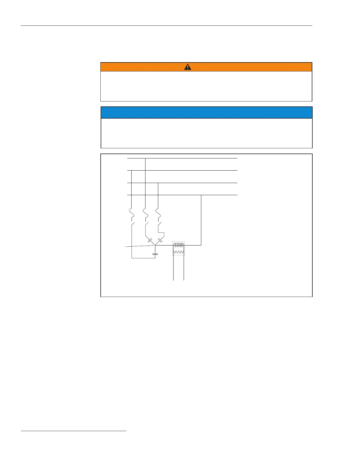
Voltage and Current
Sensing
A phase
Starpoint
To capacitor control
0-10 Vac
B phase
C phase
Neutral
Fuses
Switches
Neutral current sensor
(CT terminated on an
imbedded resistor)
The neutral voltage sensing option allows the capacitor control to monitor and
take action if it detects abnormal levels of voltage on the starpoint of an ungrounded
wye-connected bank. Use the information provided by the neutral voltage sensor manu-
facturer to design your installation. See Figure 23 on page 20.
Figure 22. Neutral current sensor installation between the starpoint and the neutral.
NOTICE
For neutral current sensing on 4-wire distribution systems where the starpoint
of the capacitor bank is tied to the neutral and/or ground, you must install the
neutral current sensor between the starpoint and the system neutral and/or ground.
See Figure 22.
Installing the Capacitor Control
20 S&C Instruction Sheet 1024-510

 Loading...