WARNING
Leave the 10-A fuse out until instructed to replace it later in the installation
process. Otherwise, dangerous unexpected bank operation may occur.
STEP 3. Install the control on the meter base, pole, or panel, in a location with
minimum trafc exposure.
All IntelliCap 2000 controls have an internal terminal strip; the terminal strip
configuration is shown on a label inside the enclosure below the faceplate. The
terminal strip wires connect to the meter base, cable connector, or cable wire
configurations shown below. A meter base with a pole-mounting bracket and
meter-ring assembly is available from S&C.
Follow these steps to install the control on the meterbase:
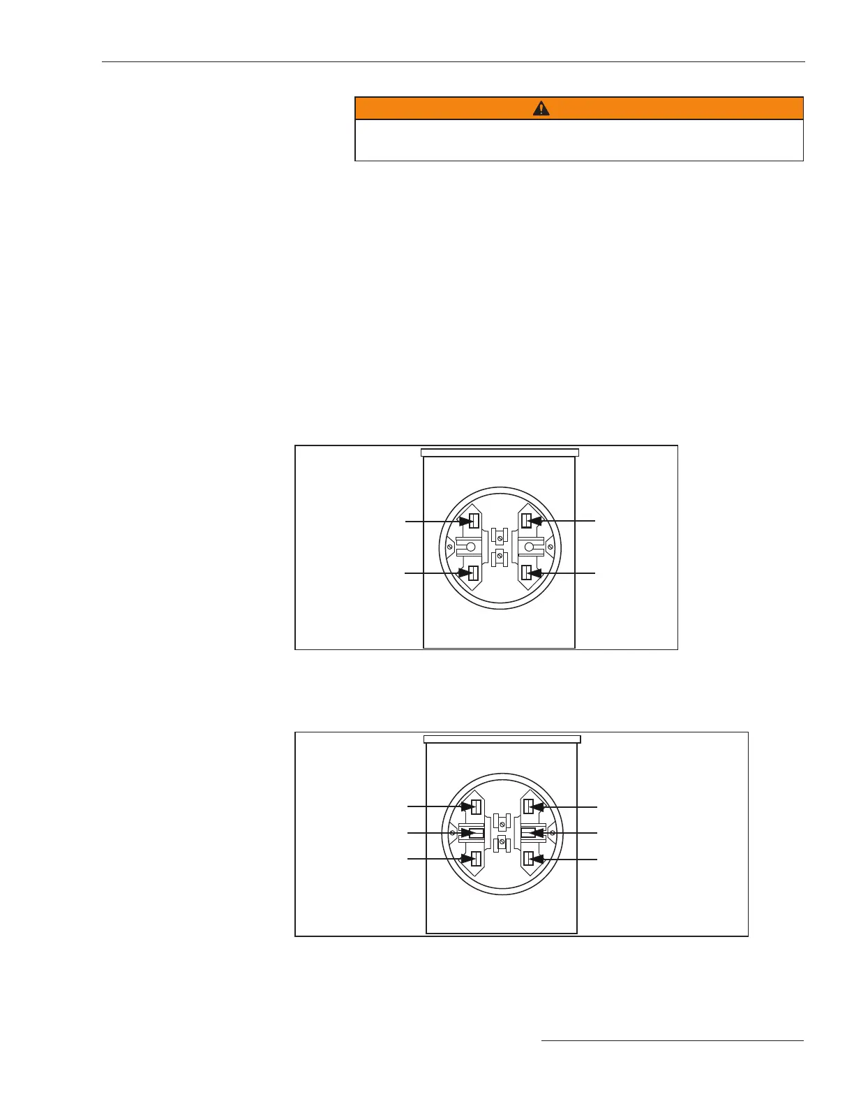
STEP 1. Conrm your meter base socket is wired correctly for this control.
The required socket wiring for a four-jaw plug is shown in Figure 3. The wiring
for each type of six-jaw meter base is shown in Figures 4 through 10. The correct
configuration for the control is also indicated by a label on the back of the control
enclosure. A meter base mount control may also have sensor cable connec-
tors on the bottom of the enclosure. See Figure 11 on page 12 for connector
locations.
Meter Base Mounting
Figure 3. Four-jaw meter base socket configuration for capacitor controls with catalog number
suffix -J40. Catalog number suffix -J41 reverses only ac line and ac neutral. Catalog number
suffix -J42 reverses only open and close.
Figure 4. Six-jaw meter base socket configuration for capacitor controls with catalog number
suffix -J60.
Ac line
Open
Ac / sensor neutrals
Close
Neutral sensor
hot
Current sensor hot
Ac line
Open
Ac neutral
Close
Installing the Capacitor Control
S&C Instruction Sheet 1024-510 9

 Loading...