Installing the Capacitor Control
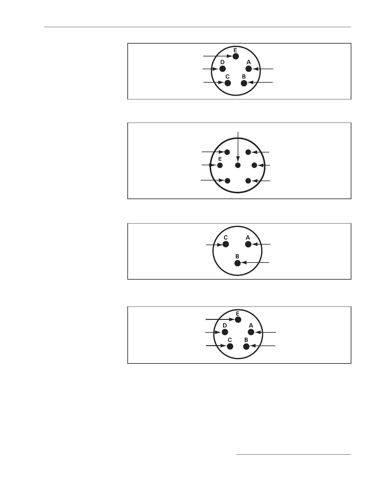
Figure 15. Bracket mount receptacle wiring configuration, five-pin for capacitor controls with
catalog number suffix -M1.
Connector Configuration—M1
Ac line
Ac neutral
Not connected
Open
Close
Figure 16. Bracket mount receptacle wiring configuration, seven-pin for capacitor
controls with catalog number suffix -M3.
Connector Configuration—M3
Ac line
Open
Close
Line current
sensor hot
Neutral current/
voltage sensor hot
Return for line &
neutral sensors
Ac neutral and shield ground
A
B
CD
E
F
G
Figure 17. Bracket mount receptacle wiring configuration, three-pin for capacitor
controls with catalog number suffix -M5, -M7, or -K1.
Shield
Sensor
return
Sensor
hot
Connector Configuration—M5
Figure 18. Bracket mount receptacle wiring configuration, five-pin for capacitor controls with
catalog number suffix -M11.
Connector Configuration—M11
Digital input 1
Digital input 2
Not connected
Return
Digital input 3
The standard plus var and current control with single-phase current sensing provided by
a customer-furnished 0-5A current transformer, catalog number 240164-J67, is designed
for mounting on the surface of a control panel. It has a special wiring harness that has
seven 3-foot (914 mm) wires that exit from the bottom of the control. A shorting block
should be connected to this harness and mounted nearby. The shorting block allows
you to safely remove the control without leaving the CT circuits open. See Table 1 on
page 17 for the harness color code; each wire is labeled on the harness.
Harness Wiring
S&C Instruction Sheet 1024-510 17

 Loading...