Front Panel Removal
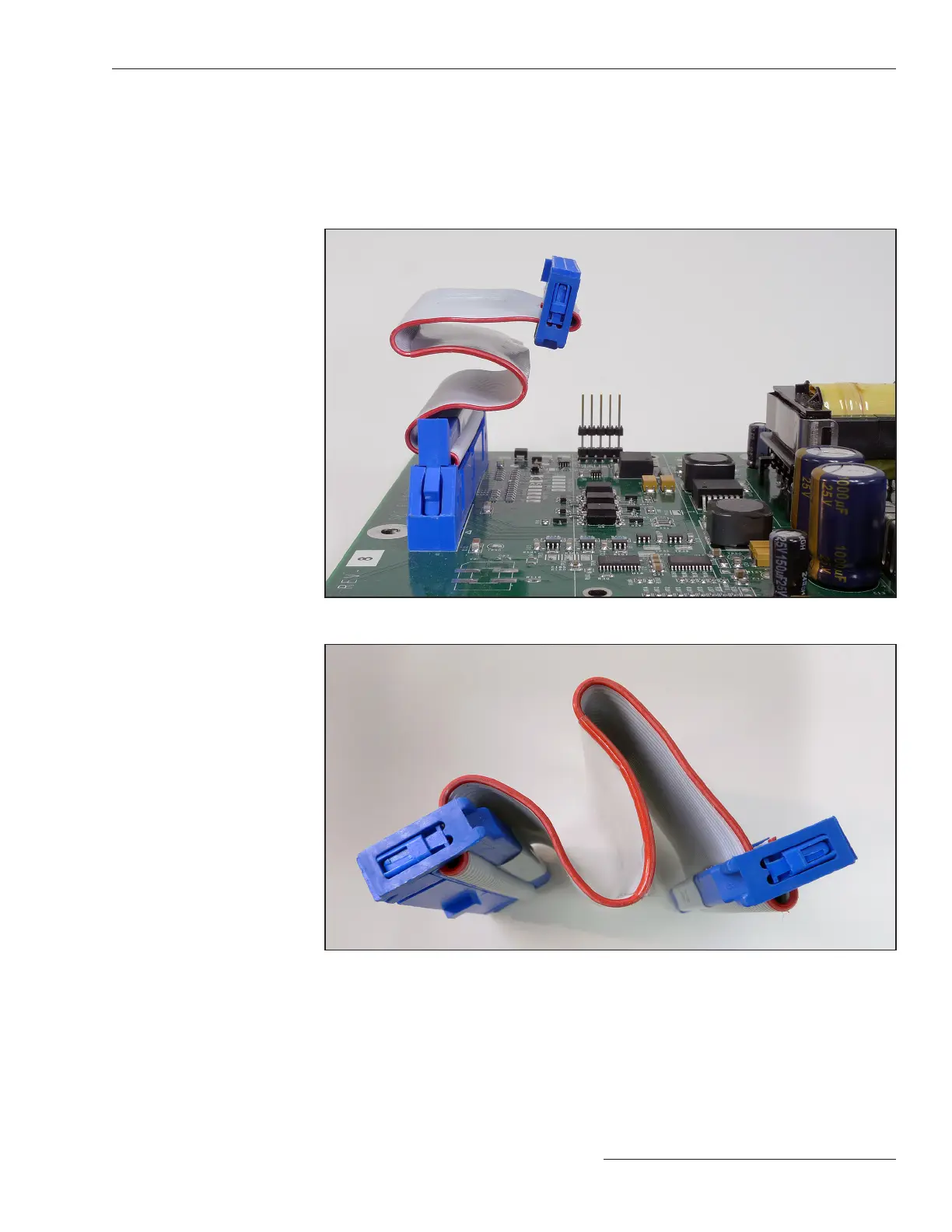
The front panel is installed close to the PS/IO board underneath it. The ribbon data cable
is shown in Figure 26. When removing the front panel, be careful that the ribbon cable
is not crimped when reinstalling the front panel. Make sure it is carefully bent to the
shape shown in Figure 27 before reinstalling the front panel. Be sure to avoid pinching
the ribbon cable between the front panel and the enclosure protrusions when reinstalling
the front panel.
Figure 26. Front panel harness installed on the PS/IO board.
Figure 27. Harness to connect front panel, bent so it will not be crimped.
This completes hardware installation and testing. Continue with Instruction Sheet
1024-530, “IntelliCap® 2000 Automatic Capacitor Control: Setup.”
S&C Instruction Sheet 1024-510 25

 Loading...