SCADA Communication Setup
SCADA Capability
The IntelliRupter fault interrupter can communicate
with a SCADA system via the DNP protocol by using
a WAN radio or ber-optic transceiver installed in the
communication module. Alternately, an appropriate
SCADA communication device can be housed in a separate
pole-mounted enclosure.
DNP Implementation
DNP implementation of the IntelliRupter fault interrupter
operating system conforms to DNP V3.00 Subset
Definitions, version 2.00, available from the DNP
Users Group. Refer to S&C Instruction Sheet 766-560,
“IntelliRupter
®
PulseCloser
®
Fault Interrupter: DNP
Points List and Implementation.”
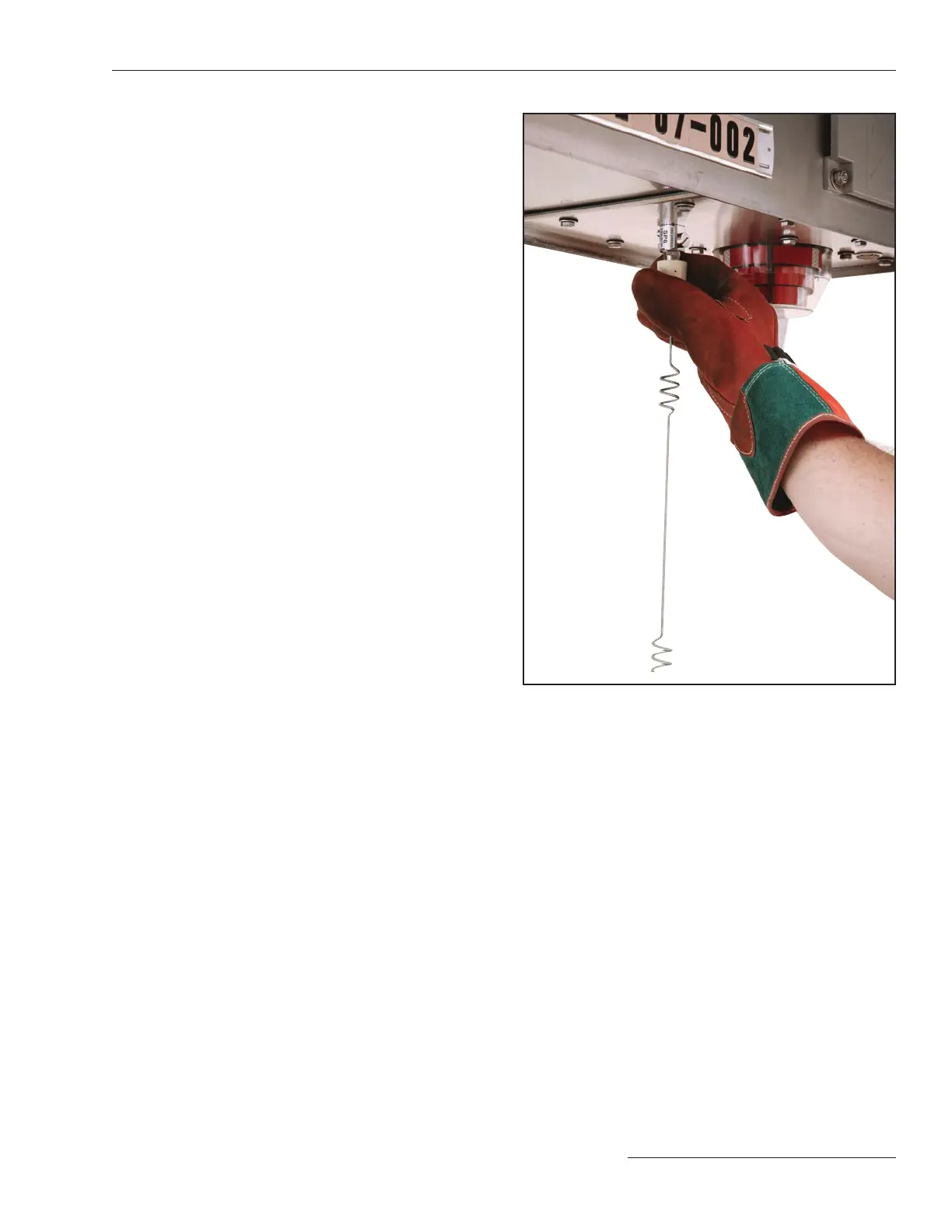
SCADA Antenna
A standard N type antenna connector for a WAN radio
is furnished on the underside of the IntelliRupter fault
interrupter base. A surge suppressor for the antenna is
mounted inside the base.
The antenna can be mounted directly to the connector
as shown in Figure 15. If the optional bracket-mounted
antenna has been furnished, the antenna is positioned
2½ feet (762 mm) horizontally from the bottom of the base.
SCADA Setup
SCADA communication setup is covered in S&C Instruction
Sheet 766-530, “IntelliRupter
®
PulseCloser
®
Fault
Interrupter: Protection and Communication Setup.”
Among the topics presented are mapping DNP analog
input and output points, status points, counter points, and
control points.
SCADA Diagnostics and Troubleshooting
SCADA communication diagnostics are covered in S&C
Instruction Sheet 766-552, “IntelliRupter
®
PulseCloser
®
Fault Interrupter: Operating and Diagnostic Instructions
for IntelliTeam
®
SG Automatic Restoration System.”
Data log messages are listed in S&C Instruction Sheet
766-561, “IntelliRupter
®
PulseCloser
®
Fault Interrupter:
Data Log Messages.”
Figure 15. SCADA antenna mounted directly to the connector
on the base.
S&C Instruction Sheet 766-520 15

 Loading...


