4
2.1 Decide on the best position for the heater taking account of paragraphs 1.2 and 1.3
and inlet and outlet connections. The float valve and overflow assembly can be fitted
on either side of the heater.
2.2 Using the template provided mark the position of the top two fixing holes. Before
drilling the wall ensure there are no hidden services such as water, gas or electrical
cables embedded in the area of the wall to be drilled.
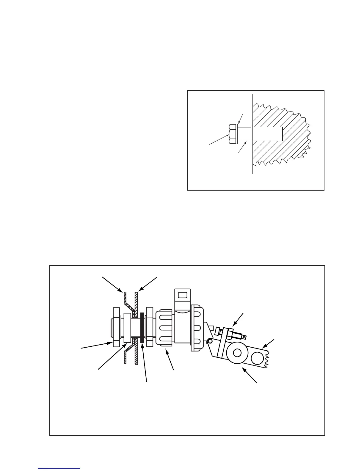
2.3 10mm wall fixings are recommended
These are not supplied
Drill the wall and insert the two top wall
fixings. Assemble the spacing collars as
shown in figure 2. Locate the heater onto
the spacing collars and mark the bottom
fixing holes. Remove the heater, drill the
wall and fit the bottom wall fixings.
2.4 Fit the float valve complete with float, to the cistern tank.The float valve is fitted
with a white seating which is suitable for inlet pressures from 1bar to 10 bar. If the
pressure is below 1 bar the seating must be swapped with the red seating attached to
the float valve arm. Access to the seating is obtained by undoing the small plastic
nut. (Refer to figure 3.)
RUBBER WASHER
ADJUSTING SCREW
WITH LOCKING NUT