DRAWING No. PC5000a 07-0812 2040 6010
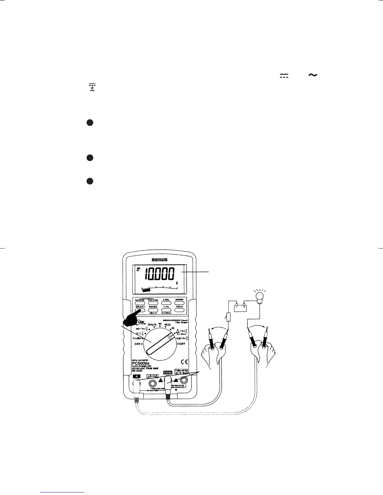
3) Measurement procedure
Connect the plug of black test lead to COM measuring input
terminal, and plug of red test lead to A measuring terminal.
Set the function switch to 'A' and select either ' ' or ' ' or
' ' by pressing the "SELECT" switch.
In the circuit to measure, apply the red and black test pins
in series with load.
For measurement of DCA, apply the black test pin to the
negative potential side of the circuit to measure, and the
red test pin to the positive potential side in series with load.
For measurement of ACA, apply the red and black test
pins to the circuit to measure in series with load.
For measurement of (AC+DC)A, apply the red and black
test pins to the circuit to measure in series with load.
Apply the red and black test pins to the circuit to measure.
Read the value on the display.
After measurement, remove the red and black test pins from
the circuit measured.
D-1034-143a PC5000(E)
—
24
—
Note:
<6A: Continuous measurement is possible. >6A: Cool down
DMM for 3 minutes after the measurement for 1 minute.
・