– 28 –
SM830092
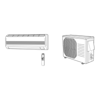
8. INSTALLATION INSTRUCTIONS
7-2. Recommended Wire Length and Wire Diameter for Power Supply System
7-3. Wiring System Diagram
Models
Time Delay
Fuse or
Circuit
Capacity
(B)
*1
Inter-unit
Wiring
(A)
*1
Power Supply
AGW #14
C2462R, CL2462R 64 ft. (AWG #12) 35 A
132 ft.
*1 Refer to the Wiring System Diagrams (See below diagram) for the meaning of “A” and “B.”
AWG = American Wire Gauge
1
2
G
4
1
2
4
G
L1
L2
G
Indoor Unit Outdoor Unit
Ground
(B)
(A)
Ground
Disconnect SW
(Field supply)
To access the electrical component box, open the air
intake grille and remove the electrical component box
cover.
Outdoor Unit: “C”, “CL” models
Single-phase
60 Hz, 208/230 V
NOTE
 Loading...