– 53 –
SM830092
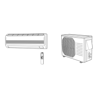
Fan motor
capacitor
Compressor motor
capacitor
1041_X_S
Multimeter
Ω
Fig. 21
3) Checking the Electrical Parts
1
Power transformer ...........................Indoor unit *Measure the coil resistance.
• Primary 230-208 V ; Measure the resistance between two WHT lead wire terminals
of socket connected to power transformer.
• Secondary 19 V ; Measure the resistance between two BRN lead wires.
2
Power transformer (TR) ................. Outdoor unit *Measure the coil resistance.
• Primary 230-208 V ; Measure the resistance between two WHT lead wire terminals
of socket jointed to power transformer.
• Secondary 19 V ; Measure the resistance between two BRN lead wires.
3
Indoor fan motor (FMI) ............... Indoor unit *Measure the coil resistance.
• Measure the resistance between each terminal of the socket connected to the
indoor fan motor.
4
Outdoor fan motor (FMO) ........... Outdoor unit *Measure the coil resistance.
• Measure the resistance in the same manner as explained above 2 .
5
Motor capacitor ............ Both in indoor and outdoor unit
• Remove the lead wires from the
capacitor terminals, and then place a
probe on the capacitor terminals as
shown in Fig. 21. Observe the deflec-
tion of the pointer, setting the resis-
tance measuring range of the multim-
eter to the maximum value.
• The capacitor is “good” if the pointer
bounces to a great extent and then
gradually returns to its original posi-
tion.
The range of deflection and the deflection
time differ according to the capacity of the
capacitor.
NOTE
12. SERVICE PROCEDURES
 Loading...