I - 50
SM830082
1
2
3
4
5
1. Specifications
HP
High
pressure
switch
Compressor
Accumulator
EC
P
Heat exchanger
4-way valve
EC
P
Heat exchanger
Distributor
Electronic
ref.control
valve
Strainer
Liquid line
nipple
Liquid line
service
valve
O.D.
3/8"
(9.52mm)
O.D.
3/4"
(19.05mm)
Gas line
nipple
Gas line
service
valve
Distributor
Sub-heat exchanger
Cooling Cycle
Heating Cycle
Strainer
M
2181_THS_I
Muffler
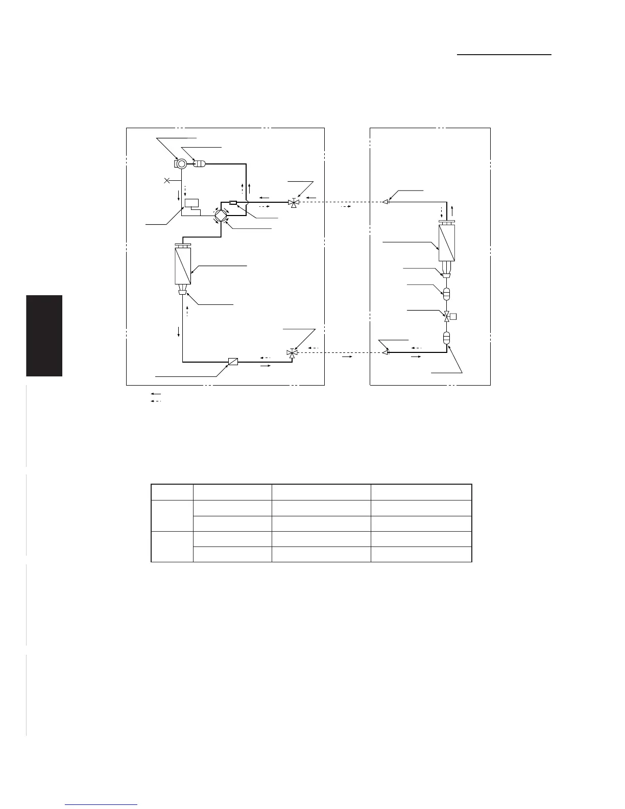
1-5 Refrigerant Flow Diagram
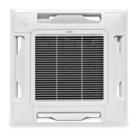
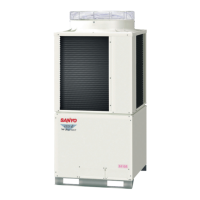
Outdoor Unit: CH4242 Indoor Unit: 42 Type
1-6 Operating Range
Temperature Indoor Air Intake Outdoor Air Intake
Cooling
Maximum 95 °F DB, 71 °F WB 115 °F DB
Minimum 67 °F DB, 57 °F WB 0 °F DB
Heating
Maximum 80 °F DB, 67 °F WB 75 °F DB, 65 °F WB
Minimum -DB / -WB 17 °F DB / 15 °F WB
 Loading...