-E14-
Using RF Modulator
If your TV does not have a Video input jack and has an antenna
terminal only, please purchase the *RF Modulator (not supplied).
(*Please consult your audio/video dealer.)
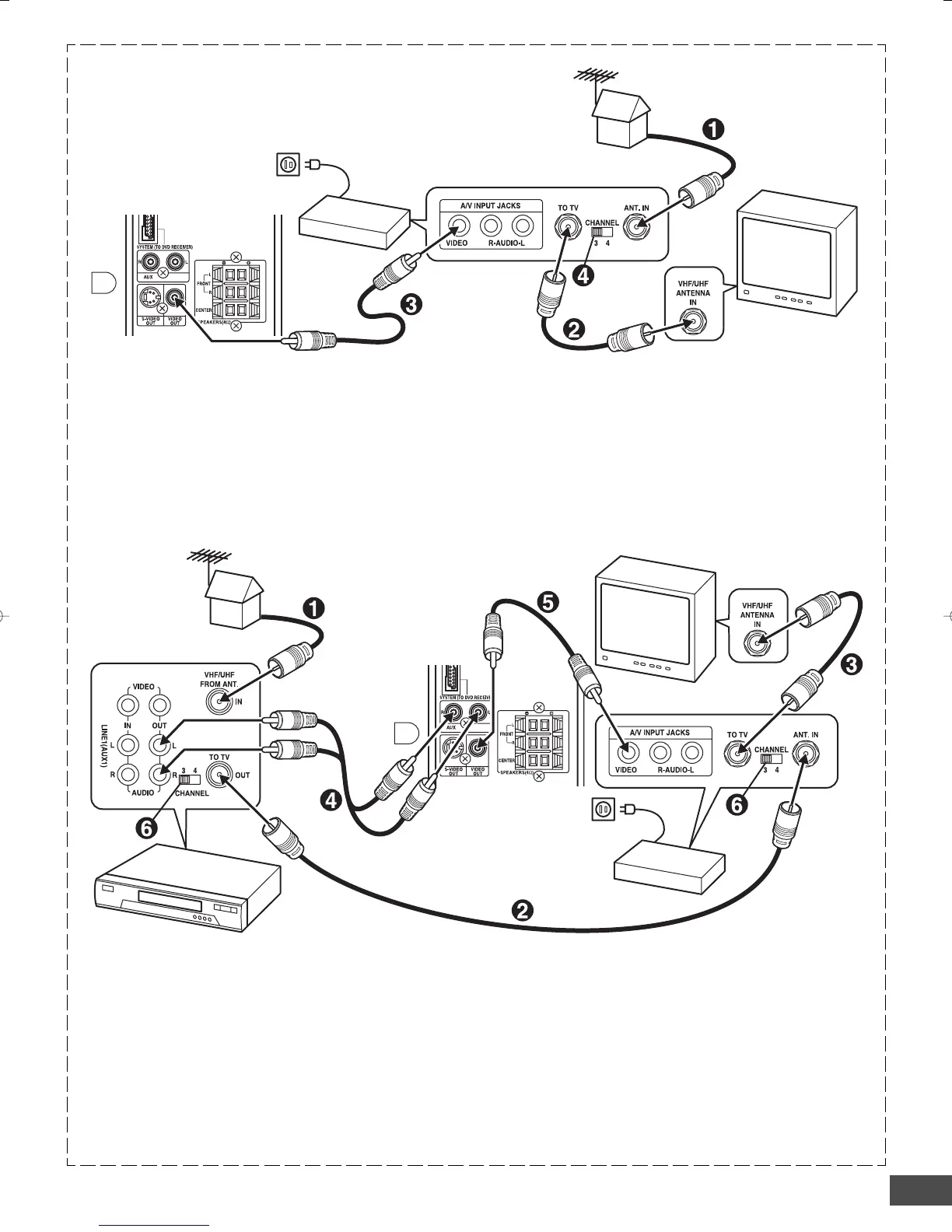
Example: Sub-woofer, TV and RF Modulator connections
1. Connect the antenna cable (not supplied) to the ANT. IN
terminal of the RF Modulator.
2. Connect the 75-ohm coaxial cable (not supplied) between
the TO TV terminal of the RF Modulator and the VHF/UHF
ANTENNA IN terminal of the TV.
3. Connect the Video cable with yellow connectors (supplied)
between the VIDEO OUT jack of the sub-woofer and the
VIDEO input jack of the RF Modulator.
Example: Sub-woofer, VCR, TV and RF Modulator connections
1. Connect the antenna cable (not supplied) to the VHF/UHF
FROM ANT IN terminal of the VCR.
2. Connect the 75-ohm coaxial cable (not supplied) between
the TO TV OUT terminal of the VCR and the ANT. IN
terminal of the RF Modulator.
3. Connect the 75-ohm coaxial cable (not supplied) between
the TO TV terminal of the RF Modulator and the VHF/UHF
ANTENNA IN terminal of the TV.
4. Connect the audio cables (not supplied) between the AUX
jacks of the unit and the AUDIO OUT jacks of the VCR. Use
the red connectors for the right-R jacks and the white
connectors for the left-L jacks.
5. Connect the Video cable with yellow connectors (supplied)
between the VIDEO OUT jack of the sub-woofer and the
VIDEO input jack of the RF Modulator.
6. Turn on the TV, and set the channel number (CHANNEL3 or
CHANNEL4) on all TV, VCR and RF Modulator, whichever
is not used for regular broadcasts in your area.
Note:
For more details, please refer to the instruction manual of the RF
Modulator.
4. Turn on the TV, and set the channel number (CHANNEL3 or
CHANNEL4) on both TV and RF Modulator, whichever is not
used for regular broadcasts in your area.
Note:
For more details, please refer to the instruction manual of the RF
Modulator.
To VIDEO OUT jack (Yellow)
To VIDEO OUT jack (Yellow)
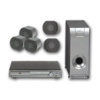
Sub-woofer (Powered speaker)
Sub-woofer
(Powered speaker)
HiFi Stereo VCR
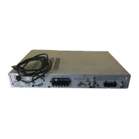
RF Modulator
RF Modulator
TV
TV
 Loading...