14
Connection on PCB
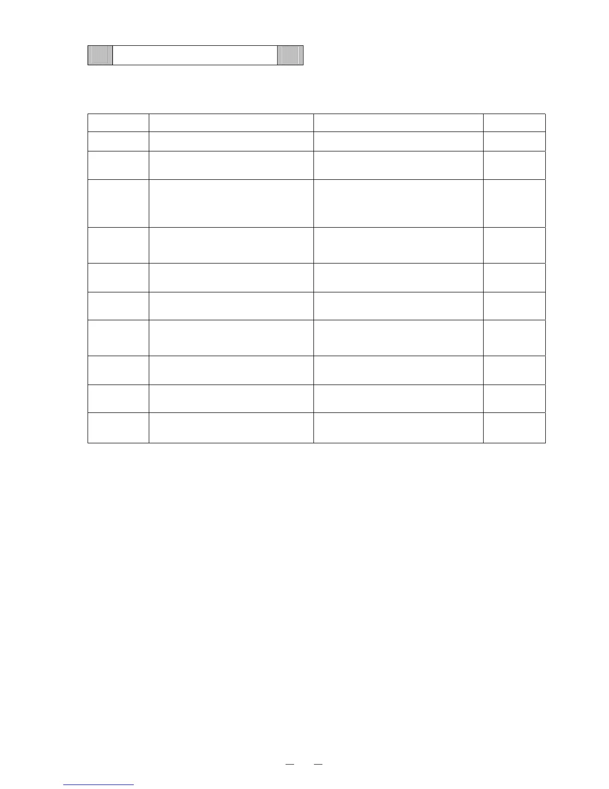
Following is the explanation of connections on Main PCB.
Connector Connects to Usage Voltage
CN1 Switching power supply To supply the power to PCB #1:12V
CN2
MTR-480(Option)
To connect with interface
CN3
Remote alarm terminal
#1: COM.
#2: N.O.
#3: N.C.
Output for remote alarm contact
CN4
#1-#2: Temp. control relay
#5-#6: Fan relay
To control chamber temperature
To conduct current to cap. tube
heater
#1-#2:12V
#5-#6:12V
CN5
#1, #7: Buzzer
#2-#6: Control PCB (CN51)
To control with each switches
CN6
Display PCB(CN52)
To connect with each LED
CN7 #7-#8: Comp. sensor
To control condensing fan motor
by the temperature in comp.
sensor
CN8 #1-#2: Battery
To supply the power to Main PCB
during power failure
#2:6V
CN9 Unused
CN11 #1-#3: Temp. sensor To detect chamber temperature