78
5
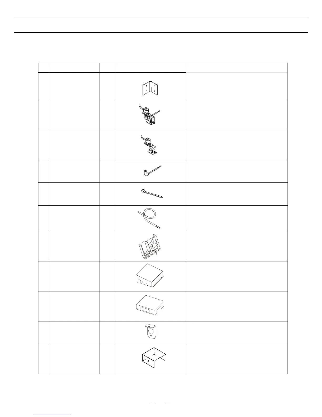
COMPONENTS LIST
Confirm that the accessories of the table 1 are gathered. Report it to the dealer or the sales if there is a
problem in packing of the product.
Table 1
No. PARTS NAME Q’ TY APPEARANCE THE EXPLANATION OF THE USE
1 PLATE MTG A 1
The plate fixes a solenoid valve cover.
2
LCO
2
SOLENOID
VALVE ASS’Y
1
It is the solenoid valve of LCO
2
. (This is
assembled by the setup.)
2-1
LCO
2
SOLENOID
VALVE
1
It is a part of the LCO
2
solenoid valve
assy.
2-2
VALVE OUTLET
PIPE
1
It is a part of the LCO
2
solenoid valve
assy.
2-3 SK BAND 2
A CO2 valve is put in the chamber, and it
is the part which fixes insulation.
3
LCO
2
JOINT PIPE
AND JOINT
PACKING
1
The pipe which connects a LCO
2
gas
cylinder and the LCO
2
solenoid valve.
4
BACK-UP
SYSTEM
1
LCO
2
is injected when a freezer has
temperature rise.
5
SOLENOID VALVE
COVER
1
This cover is a protection of the LCO
2
solenoid valve.
6
BACK-UP SYSTEM
COVER
1
This cover is a protection of the back-up
system.
7
VALVE PLATE
MTG
1
This plate fixes a valve cover.
8 VALVE COVER 1
This cover protects a valve outlet pipe in
the chamber.