79
6
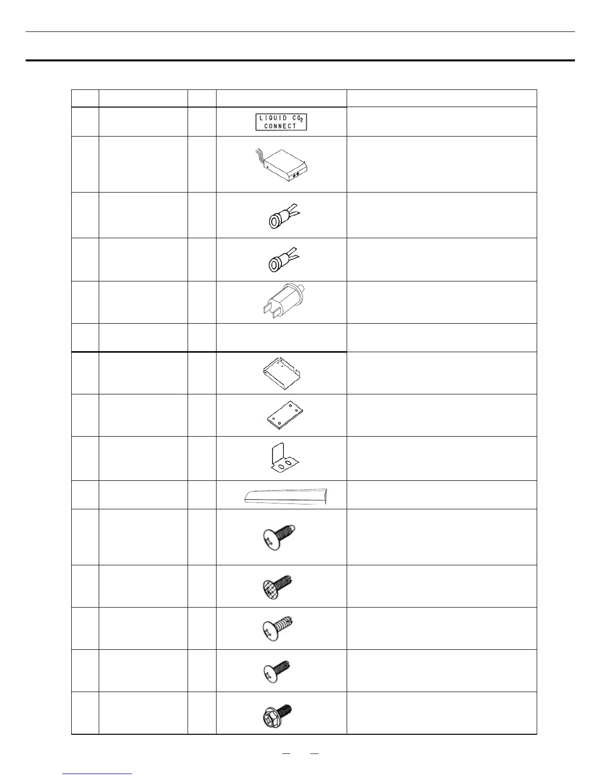
COMPONENTS LIST
The continuation of the table 1
No. PARTS NAME Q’ TY APPEARANCE THE EXPLANATION OF THE USE
9 LABEL 1
It is put near the connection place.
10
DOOR SWITCH
ASS’Y
1
This assy connected a door switch and
two indicator lamps (green and orange).
10-1
INDICATOR
LAMP (GREEN)
-
It is the lamp turned on with a power
switch of the back-up system. 䋨 It is
attached.䋩
10-2
INDICATOR
LAMP (ORANGE)
-
It is the lamp turned on when the battery
of the backup system declines. 䋨 It is
attached.䋩
10-3 DOOR SWITCH -
When the door of the freezer opens and
closes, it is the switch which does on-off.
䋨It is attached.䋩
10-4
WIRING ASS’Y
DS
1 Refer to the Fig. of Page12.
These wires are the indicator lamp and
the door switch. 䋨It is attached.䋩
11
DOOR SWITCH
MTG PLATE
1
It is a plate which fixes a door switch
ass’y.
12
SHIM (for DOOR
SWITCH MTG
PLATE)
1
It is a plate to lay under the door switch
mounting plate.
13 STRIKE PLATE 1
It is fixed on the door of the freezer, and it
is the part that on-off does a door switch
by the open/close of the door..
14 WIRE COVER 2
This cover fixes the wiring ass’y DS of the
door switch ass’y.
15
SCREW A M4䌸10
(C TIGHT)
11
For nylon clip 6N䋨1䋩䇮For Nylon clip 7N
䋨2䋩䇮For back-up system䋨2䋩䇮For solenoid
valve䋨4䋩䇮For mounting plate䋨2䋩
16
SCREW B M4䌸10
(STAINLESS)(CO
LORED HEAD)
7
For solenoid cover䋨4䋩䇮For door switch ass’y
䋨3䋩
17
SCREW C M4䌸10
(STAINLESS)
2
For valve cover
18
SCREW D M5䌸10
(STAINLESS)
2
For strike plate
19
SCREW E M5䌸16
(PAN HEAD)
2
For door switch mounting plate