-14-
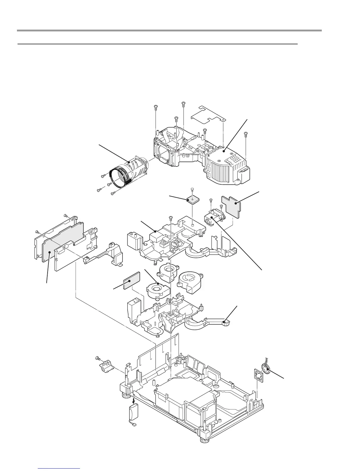
Mechanical Disassembly
v Optical unit, NETWORK board, Buzzer, Temp., Line Filter board,Fans removal
Fig.4
Temp. board
SP901
Projection lens
Noise filter
Optical unit
(T3x6)x2
(T3x8)
(M2.5x8)x4
(T3x8)x2
(T3x6)
Line filter board
FN904
FN903
FN905
Buzzer board
Battery
(M3x10)
Duct bottom
1. Remove the Optical unit.
2. Remove the NETWORK board.
3. Remove the Battery and Buzzer board.
3-1. Remove Screw (T3x8) and 4 hooks on the duct and then remove the
Duct.
3-2. Remove the Duct top and then remove the Buzzer board.
4. Remove the Line filter board and Temp. board.
5. Remove fans (FAN903,FAN904,FAN905) and SP901.
Duct top
NETWORK board
(T3x8)x5
 Loading...