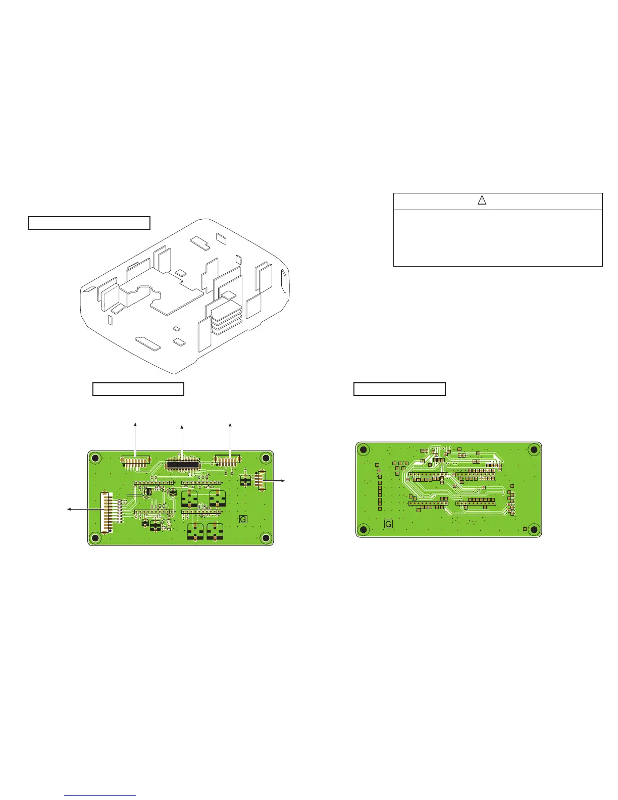
EasyManua.ls Logo

Sanyo PLC-XF47 - Printed Wiring Board Diagrams

Sanyo PLC-XF47
220 pages
To Next Page IconTo Next Page
To Previous Page IconTo Previous Page
Loading...
PCB_KE3A A13
Printed Wiring Board Diagrams
This projector is isolated from AC line by using the internal converter transformer.
Please pay attention to the following notes in servicing
1. Do not touch the part on hot side (primary circuit) or both parts on hot and cold sides
(secondary circuit) at the same time.
2. Do not shorten the circuit between hot and cold sides.
3. The grounding lead must be connected to the ground of the same circuit when meas-
uring of voltages and waveforms.
CAUTION
Te
rminal boar
d
M
ot
or
PFC 3-4
Ballast
3
Ballast
4
Sub po
w
er
PFC 1-2
Po
w
er
CG
M
ot
her
Co
n
trol
Re
a
r LED
Ballast
2
Ballast
1
RS232C
M
ai
n
EXH F
an net
R/C
2
Lamp net
Fr
o
nt LED
RG
B
in F
an net
N
et
R/C
1
PBS F
annet
Se
n
sor
SW
-P
ow
r
supply
AC
net
F-
G net
Lam
p fannet
1AA4B10C5850A
PWB.MOTOR KE3A
A_SIDE
1
10
IC1601
1
10
IC1611
1
10
IC1621
1
10
IC1631
L1601
L1602
L1603
L1604
L1605
L1606
L1607
L1608
40
39
2
1
K16A
1
4
K16B
1
7
K16C
11
1
K16G
6
1
K16J
C1602
C1603
C1611
C1612
C1613
C1614
C1615
C1621
C1622
C1623
C1624
D1601
D1603
R1601
R1602
R1603
C1631
C1632
C1633
C1634
D1611
D1612
D1613
R1611
R1612
R1613
R1614
C1641
C1642
C1643
Q1641
D1621
C1646
Q1642
D1622
D1623
R1621
R1622
R1623R1624
C1653
C1654
D1631
C1656
D1632
D1633
R1631
R1632
R1633
R1634
D1641
R1641
R1642
R1643
R1644
C1893
C1894
C1895
A30C5
MOTOR (side-A)
LENS SHIFT VERTICAL
SENSOR SW
FRONT LED
K68B
LENS NET
K96P
B_SIDE
1
10
IC1601
1
10
IC1611
1
10
IC1621
1
10
IC1631
K16C
A30C5
MOTOR (side-B)
PWB assemblies location
MAIN
K8E
R/C 1
K68E

Other manuals for Sanyo PLC-XF47

Related product manuals