-9-
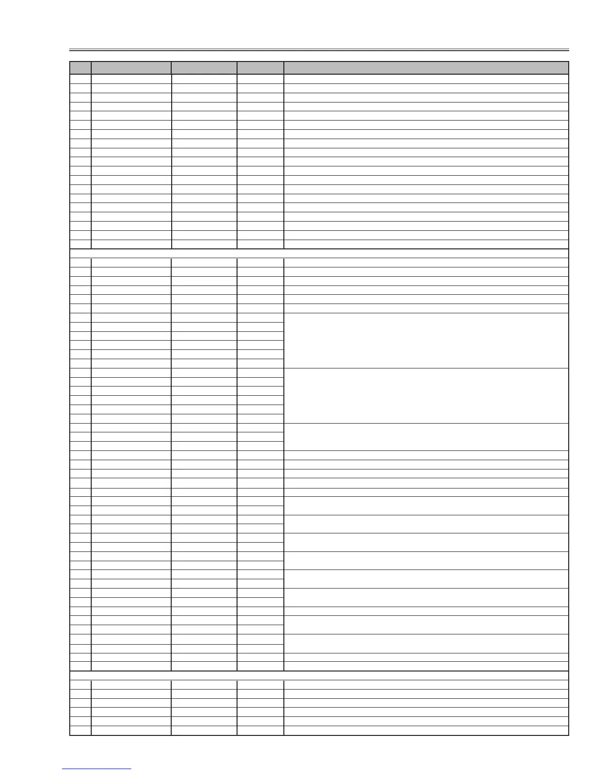
Electrical Adjustments
2 Shootout Mode 0 0 ~ 1 0: Disable 1: Enable
3 Cooling Time 3 0 ~ 15 Set cooling period, 1: 30 sec. 3: 90 sec. 15: 450 sec. 0: continuos
4Hi-Land SW 0 0 ~ 1 0: Normal 1: Highland mode (Fan spin speed max.)
5V-Douki SW 0 0 ~ 1 0: Synchronized Vertical 1: non-synchronized Vertical
6 Lamp Total Time - 0 ~ 65535 Read only
7 Net Board RESET 1 0 ~ 1 0: Disable 1: Enable
8Keystone Option 0 0 ~ 1 0: Maximum correction (fix) 1: Changeable for Input signal
9 Syukka SW 0 0 ~ 10 Set 10 to Shipping Condition
10 Color Shading SW 1 0 ~ 1 0: OFF 1: ON
11 RC Enable/Disable 0 0 ~ 3 0: Both enable 1: Front Disable 2: Rear Disable 3: Both Disable
12 Lamp Dim Level 15 0 ~ 15 0: the darkest 1: the brightest
13 Lamp Warning Time 1500 0 ~ 65535 Unit = hour
14 Forced NOBRAND 0 0 ~ 1 0: Normal 1: No brand
15 Forced Video Mute Off 0 0 ~ 1 0: Video Mute ON 1: Video Mute OFF
16 ANZEN FAN Control Fix SW 0 0 ~ 4 0: Normal 1: Normal min. 2: Normal max 3: Eco min. 4: Eco max
17 DJTR_SW - - Not used
18 HDCP Option 0 0 ~ 3 0: XGA 1: Not XGA
19 HDCP Reset 0 0 ~ 10 Set 10 and write EDID Data for HDCP
20 Auto PC Adj. 0 0 ~ 1 0: Auto PC adj available, 1: Auto PC adj. not available
Group: 11 FAN (Fan Control)
0FAN_TEMP_A_WARNING 460 30 ~ 1000 Temperature to judge abnormal A (Not memorized) Inside projector
1FAN_TEMP_B_WARNING 800 30 ~ 1000 Temperature to judge abnormal A (Not memorized) Lamp
2FAN_TEMP_C_WARNING 510 30 ~ 1000 Temperature to judge abnormal A (Not memorized) LCD Panel
3FAN_TEMP_B-A_WARNING 520 0 ~ 1000
4FAN_TEMP_C-A_WARNING 200 0 ~ 1000
5FAN_CONTROL_SW 0 0 or 1 0: Auto-control all Fans 1: Manual control all Fans
6FAN1 Manual Out 1350 0 ~ 2000 These are effective when FAN_CONTROL_SW is set to "1".
7FAN2 Manual Out 1350 0 ~ 2000
8FAN4 Manual Out 1350 0 ~ 2000
9FAN5 Manual Out 1350 0 ~ 2000
10 FAN6 Manual Out 1350 0 ~ 2000
11 FAN7 Manual Out 1350 0 ~ 2000
12 FAN1 Now Out - Read only Reading voltage of each Fan
13 FAN2 Now Out -
14 FAN4 Now Out -
15 FAN5 Now Out -
16 FAN6 Now Out -
17 FAN7 Now Out -
18 Temp Monitor A - - Read only
19 Temp Monitor B - -
20 Temp Monitor C - -
21 Pressure Monitor - - Read only
22 FAN_BALLAST_SW 0 0 or 1 Fan control depend on Ballast Output Voltage 0: OFF 1: ON
23 Service Target MODE -1 -1 ~ 3 -1: Current Mode 0: Normal Mode 1: Eco Mode
24 Service Target FAN 0 0 ~ 5 Service taget 0: FAN1 1: FAN2 2: FAN4 3: FAN5 4: FAN6 5: FAN7 ✻ Fan adjustment [Setting]
25 Control Switch 0 Control Switch for the operated Fan 0: Auto 1: Manual
26 Temp Source Range High 400 Control range of Temperature for Temperature Sensor A
27 Temp Source Range Low 330
28 Temp Fan-Out Range High 1350 / 1000 Control range of Fan control voltage by Temperature Sensor A
29 Temp Fan-Out Range Low 780 / 700 / 1000
30 Diff (UP)Src Range High 180 Difference of temperature between temp-A and temp-C for Fan additional voltage (upward)
31 Diff (UP)Src Range Low 150
32 Diff(DWN)Src Range High 80 Difference of temperature between temp-A and temp-C for Fan additional voltage (downward)
33 Diff(DWN)Src Range Low 60
34 Press Source Range Low Control range of Pressure Sensor
35 Press Source Range High
36 Press FanAdd Range High 0 Control range of Fan additional voltage by Pressure sensor
37 Press FanAdd Range Low 500
38 Ceil-Add Fan additional voltage when ceiling
39 Fan Out Limit Volt MAX 1400 Limit voltage of current Fan output voltage
40 Fan Out Limit Volt MIN. 650
41 Fan Out Limit DAC MAX 0 ~ 255 Limit of DAC output for current Fan ✻ Fan adjustment [max.]
42 Fan Out Limit DAC MIN. 0 ~ 255 ✻ Fan adjustment [min.]
43 Manual Out 0 ~ 2000 Output voltage of current Fan at manual mode
44 Now Out - Reading voltage of current Fan
Group: 12 PC Real / AV Cinema
0 PC Real Contrast 32 0 ~ 63
1 PC Real Brightness 32 0 ~ 63
2 PC Real Color 32 0 ~ 63
3 PC Real Tint 32 0 ~ 63
4 PC Real Red 32 0 ~ 63
5 PC Real Green 30 0 ~ 63
No. Adjustment Item Initial Value Range Input source / Description