-17-
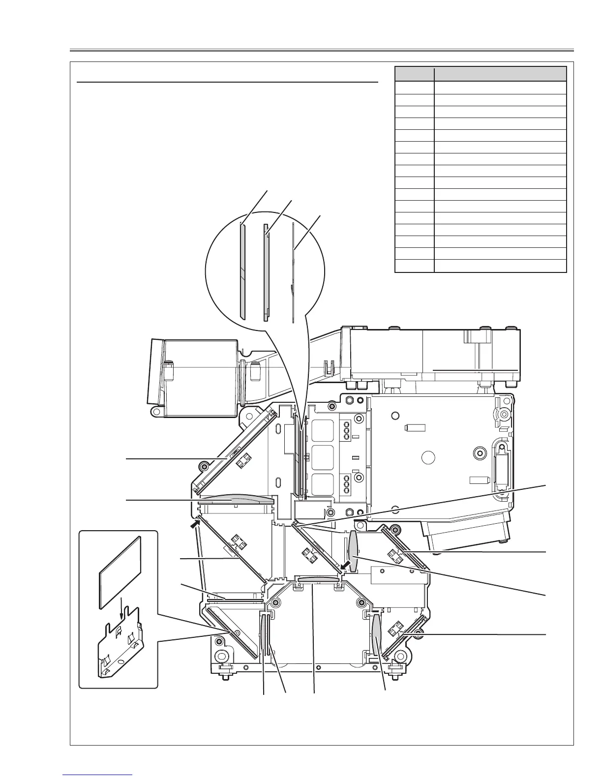
Optical Parts Disassemblies
When the optical parts in the optical unit mounting or assembling, the
parts must be mounted in the specified location and direction as
shown in figure below.
Note: The arrow in the figure below is indicated that there is the direc-
tion of part placement. Place each part as the printed marker on
the part comes to each arrow direction.
The key No. 16 should be placed as the film attached side
comes to the mirror side.
14
10
8
Fig.8
3
1
2
9
Locations and Directions
5
6
1 Slit-Int
2Integrator Lens-Out
3 PBS (Prism Beam Splitter)
4 Mirror (W-Cold)
5 Condenser lens-Out
6 Dichroic mirror (B)
7 Optical Filter (UV Cut)
8 Mirror Holder
9 Mirror (B)
10 Condenser lens
11 Dichroic Mirror (G)
12 Condenser Lens (G)
13 Relay lens-In
14 Mirror (R)
15 Condenser Lens (R)
16 Pre-polarized glass (B)
Key No. Description
4
12
11
7
13
15
14
16

 Loading...